
Blind estimation of control channel

a control channel and blind estimation technology, applied in the field of blind estimation of control channels, can solve problems such as exploiting certain dynamic ranges, and achieve the effect of reducing the amount of control information for the control channel

Active Publication Date: 2012-04-24
NOKIA TECHNOLOGLES OY
View PDF12 Cites 0 Cited by
  • Summary
  • Abstract
  • Description
  • Claims
  • Application Information

AI Technical Summary

Benefits of technology

The patent text describes an improved control signaling scheme for reducing the amount of control information for a control channel. The method involves determining the total number of allocation blocks, selecting a format for resource allocation within the allocation blocks, decoding the allocation blocks using the selected format, and performing error checking until no error is revealed. This approach allows for a blind estimation of the format chosen for the control channel information and reduces the amount of control signaling needed. The method may also involve receiving information about the total number of allocation blocks and identifying user- or terminal-specific identification for error checking. The patent text also describes a network device that decides on the total number of allocation blocks and provides this information to users. Overall, the patent text provides a technical solution for efficient control signaling in communication networks.

Problems solved by technology

One of the problems with the power control option is that only a certain dynamic range can be exploited due to hardware limitations.
A problem faced when decoding the control channel is that the receiving end will have to know the size and / or length of the data information being decoded (in order to do channel decoding and error checks) prior to the actual decoding.

Method used


Image

  • Blind estimation of control channel
  • Blind estimation of control channel
  • Blind estimation of control channel

Examples


Embodiment Construction

[0008]A need therefore exists for providing an improved control signaling scheme, by means of which the amount of control information for the control channel can be reduced.

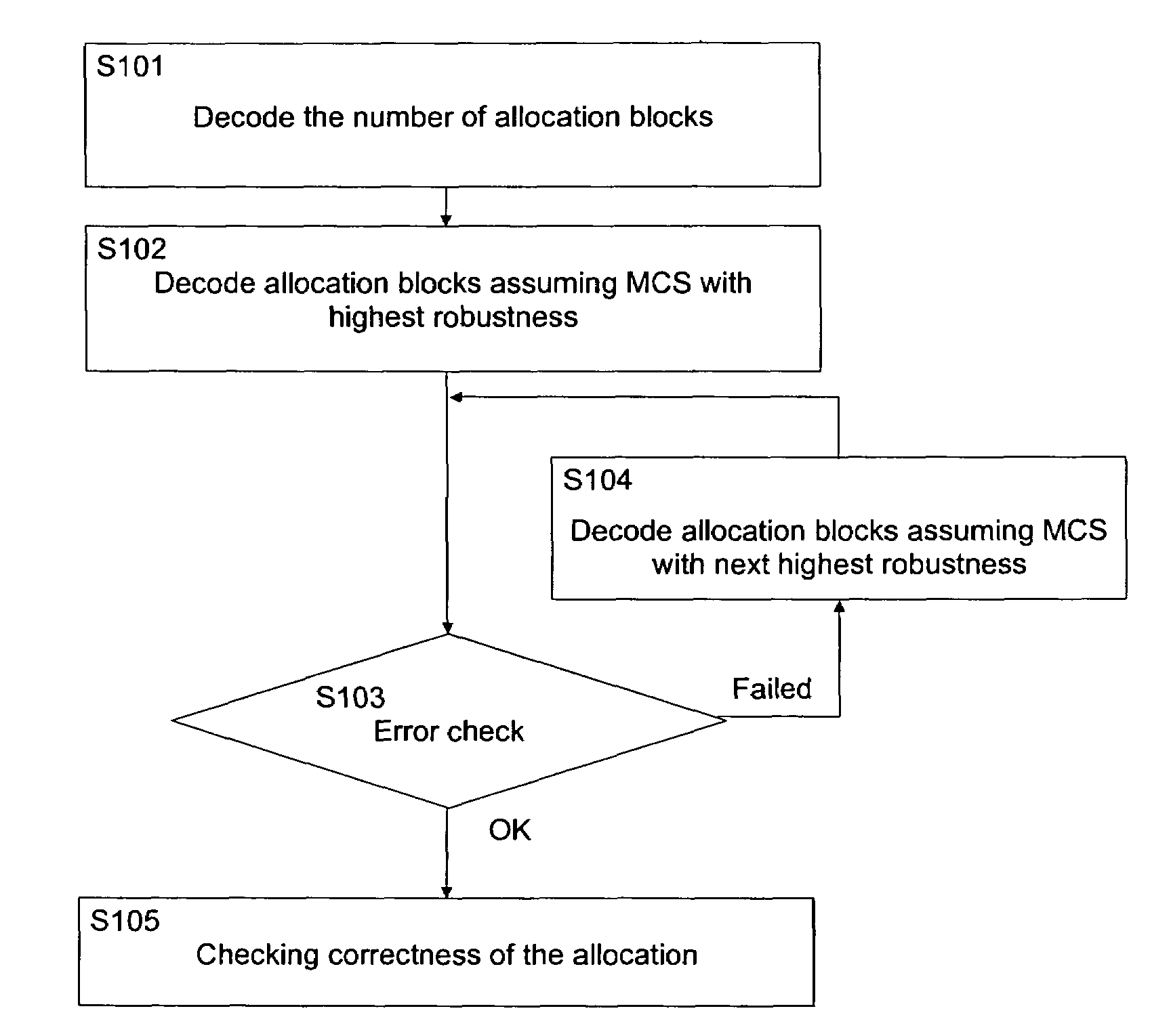
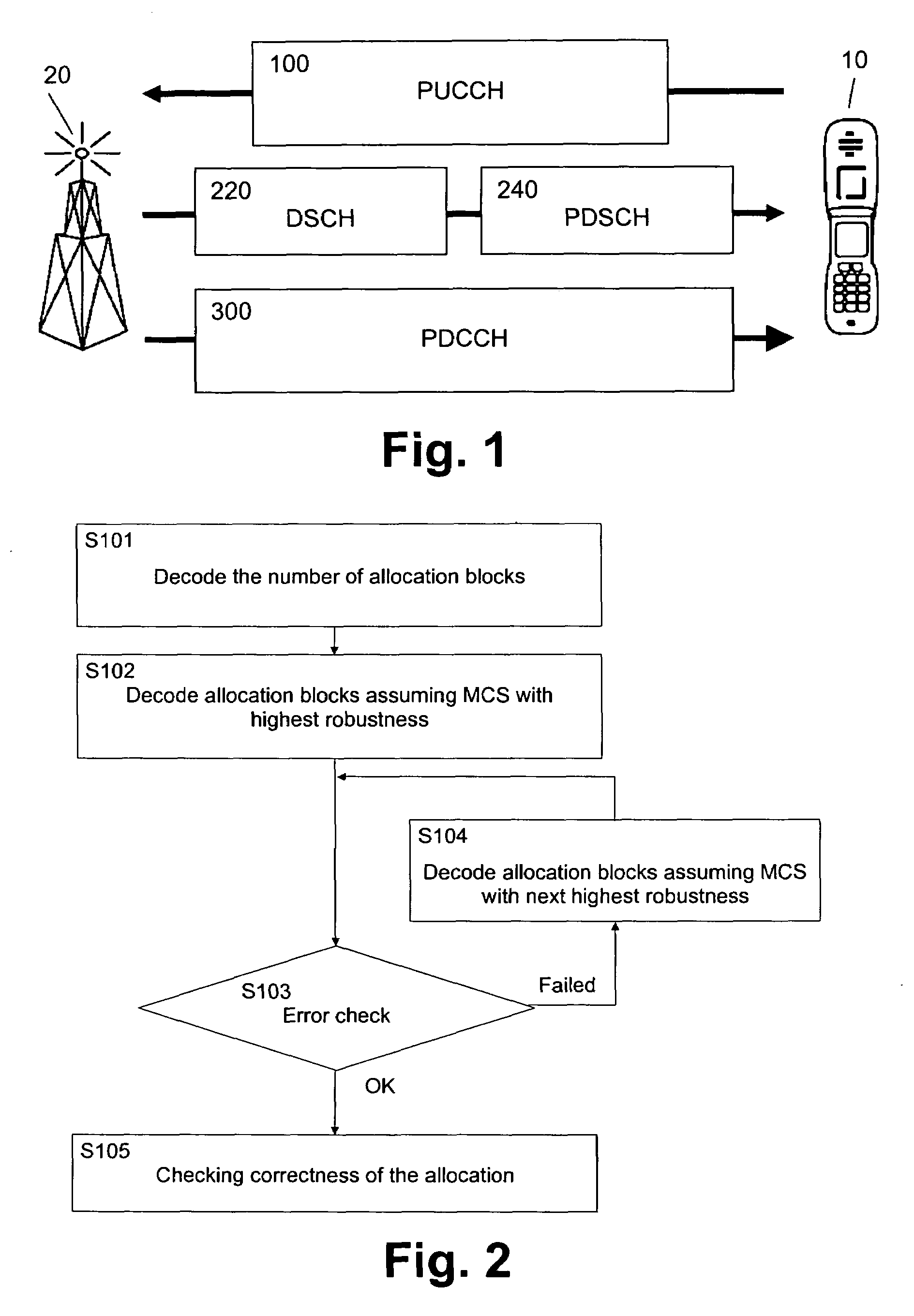
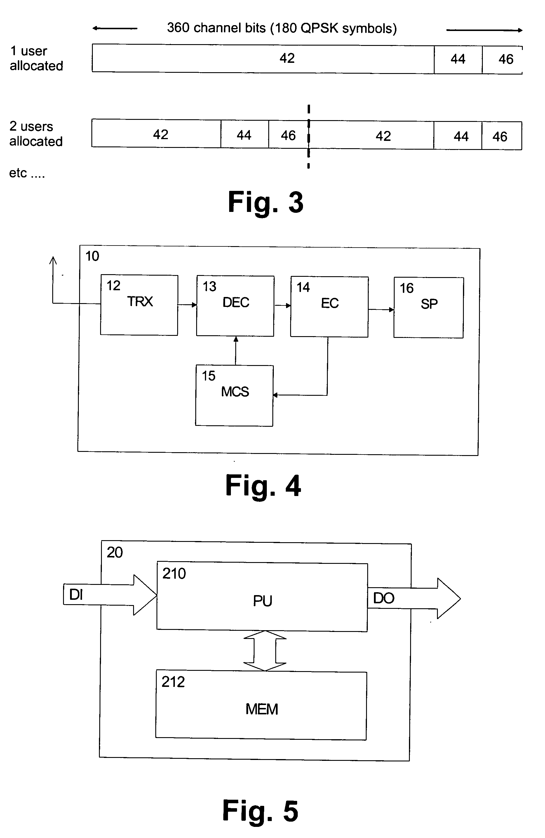
[0009]According to an embodiment of the invention, a method comprises:[0010]determining a total number of allocation blocks defining control channels to be allocated to users for at least one of uplink and downlink directions;[0011]selecting a format which determines resource allocation within allocation blocks;[0012]decoding an allocation block using said selected format;[0013]performing an error checking for said decoded allocation block; and[0014]repeating said selecting, decoding and error checking for different available formats until no error is revealed in said error checking.

[0015]According to another embodiment of the invention, an apparatus comprises[0016]a determination unit for determining a total number of allocation blocks defining control channels to be allocated to users for at least one of uplink...


PUM


Abstract

A method, system, apparatus, and computer program product for decoding control information, wherein a total number of allocation blocks defining control channels to be allocated to users for at least one of uplink and downlink directions is determined. Then, a format which determines resource allocation within allocation blocks is selected, allocation blocks are decoded using the selected format, and an error checking is performed for the decoded allocation blocks. This selecting, coding and error checking is repeated for different available formats until no error is revealed in said error checking. Thereby, a blind estimation of a format chosen for the control channel information can be achieved, so that additional amount of control signalling can be reduced.

Description

FIELD OF THE INVENTION[0001]The invention, according to various embodiments, relates to a method, system apparatus, and computer program product for decoding a control information conveyed via a control channel.BACKGROUND OF THE INVENTION[0002]In wireless communication systems, such as the long term evolution (LTE) of the Universal Mobile Telecommunications System (UMTS) Terrestrial Access Network (UTRAN) in 3rd Generation Partnership Project (3GPP), new functionalities or features for data channels, such as fast link adaptation, hybrid automatic repeat request, or fast scheduling in case of high speed downlink packet access (HSDPA), rely on rapid adaptation to changing radio conditions. To implement these features, a control channel is used to carry control information relevant for those terminal devices (or user equipments (UEs) in 3G terminology) for which data is available on the respective channel.[0003]An adaptive modulation and coding concept may be applied to the control cha...

Claims


Application Information

Patent Timeline
Patent Type & Authority Patents(United States)
IPC IPC(8): H03M13/00
CPCH04L1/0072H04L1/0046H04L1/0006H04L1/0029H04L1/0061H04L1/0038
Inventor FREDERIKSEN, FRANK
Owner NOKIA TECHNOLOGLES OY
Learn More