Methods of measuring image-sticking of a display
a technology of image-sticking and display, which is applied in the field of measuring the phenomenon can solve the problems of inability to apply a method practically, inability to determine the level of image-sticking according to the brightness, and inability to accurately measure the level of image-sticking on the display
- Summary
- Abstract
- Description
- Claims
- Application Information
AI Technical Summary
Benefits of technology
Problems solved by technology
Method used
Image
Examples
first embodiment
The First Embodiment
[0045]First, a display having N gray levels is provided. In an embodiment of the present invention, the display comprises a LCD. In another embodiment, the display comprises a plasma display panel.
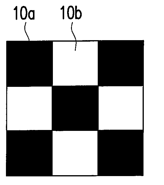
[0046]Next, an image-stick test frame is displayed on the display, as shown in FIG. 1, the image-stick test frame is composed of at least a first pattern 10a having a low gray level and at least a second pattern 10b having a high gray level. In an exemplary embodiment, the gray level of the first pattern 10a may be gray level 1, and the gray level of the second pattern 10b may be gray level N. Moreover, distributions of the first pattern 10a and the second pattern 10b of the image-stick test frame are diverse. For example, in an embodiment of the present invention, the distribution of the first pattern 10a and the second pattern 10b of the image-stick test frame comprises a chessboard distribution (shown as FIG. 1). In another embodiment, the first pattern 10a of the im...
second embodiment
The Second Embodiment
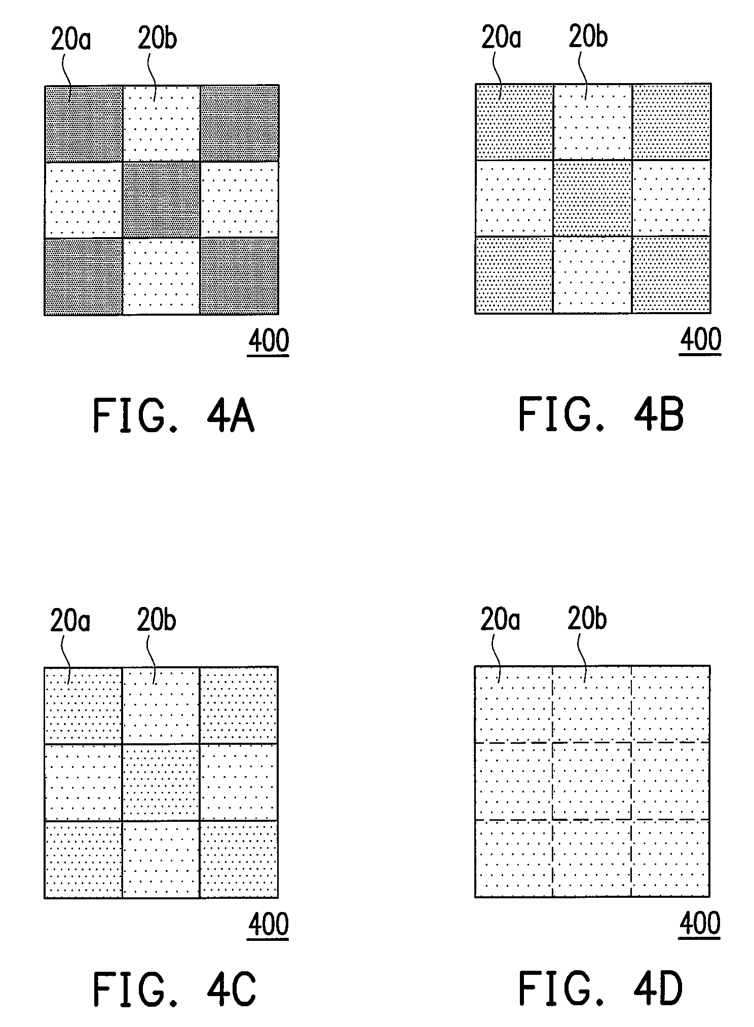
[0065]To improve the measuring accuracy of the image-sticking phenomenon of the displays, an optical measuring instrument (not shown) is further provided for judging whether the boundary of the images between the image-stick region 20a and the non-image-stick region 20b shown in FIGS. 4A˜4D is the lightest. The optical measuring instrument includes a luminance meter, a calorimeter and a spectrometer. The optical measuring instrument measures the images displayed on the image-stick region 20a and on the non-image-stick region 20b, and obtains a first value and a second value. When the first value and the second value are identical, the boundary of the images between the image-stick region 20a and the non-image-stick region 20b is the lightest (as shown in FIG. 4D).
[0066]In detail, if the optical measuring instrument is the luminance meter, the first value and the second value are brightness values. Thus, judging of the lightest boundary of the images between the ...
third embodiment
The Third Embodiment
[0067]Besides the measuring method described in the first and the second embodiments, the present embodiment provides another method for automatically measuring an image-sticking phenomenon, which will be described as follows. The present invention provides another method of measuring the image-sticking phenomenon of a display. First, a display having a plurality of pixels is provided. Next, an image-stick test frame is displayed on the display. As shown in FIG. 1, the image-stick test frame is composed of at least a first pattern and at least a second pattern 10b, wherein the gray level of the first pattern 10a is different from that of the second pattern 10b, or as describe in the first embodiment, the gray level of the first pattern 10a is gray level 1, and the gray level of the second pattern 10b is gray level N. In addition, it would be understood by those skilled in the art, arrangement of the image-stick test frames can be adjusted according to the actual ...
PUM
| Property | Measurement | Unit |
|---|---|---|
| time | aaaaa | aaaaa |
| frequency | aaaaa | aaaaa |
| optical measuring | aaaaa | aaaaa |
Abstract
Description
Claims
Application Information
 - R&D
- Intellectual Property
- Life Sciences
- Materials
- Tech Scout
- Unparalleled Data Quality
- Higher Quality Content
- 60% Fewer Hallucinations
Browse by: Latest US Patents, China's latest patents, Technical Efficacy Thesaurus, Application Domain, Technology Topic, Popular Technical Reports.
© 2025 PatSnap. All rights reserved.Legal|Privacy policy|Modern Slavery Act Transparency Statement|Sitemap|About US| Contact US: help@patsnap.com


