
Portable electro-mechanical signal system

a signal system and electromechanical technology, applied in traffic signals, instruments, roads, etc., can solve the problems of inconvenient traffic stop, inconvenient placement, and insufficient traffic stop time, etc., to achieve convenient placement and sufficient traffic stop time

Active Publication Date: 2012-04-24
FISHER PHILLIPS VICTORIA C
View PDF19 Cites 41 Cited by
  • Summary
  • Abstract
  • Description
  • Claims
  • Application Information

AI Technical Summary

Benefits of technology

[0041]The signal system configuration in detail herebelow assures timely slow / stop signal recognition and reaction by approaching motorists in vehicles traveling along a roadway. The thoughtful construct and dynamic mechanization set forth in this disclosure promote sufficient traffic stopping time before a child crosses a roadway intersection or before roadway workers enter harm's way. Unlike earlier transportable traffic control units and hand-wielded signs, the unique system presented herein is easily placed into position. Moreover it is uniquely configured and operable to become increasingly prominent (i.e., physically wider) in terms of viewable profile and illumination impact during its remotely controlled, multi-staged signal phases in the face of oncoming motorists.
[0042]Uniquely, this signal system affords numerous advantages:1) a clear, mechanized signal signage that is freestanding and can be seen and unmistakably interpreted from a considerable distance;2) a steadily enhanced or broadening physical presence viewed by motorists approaching in vehicles along a roadway particularly when the system functions sequence from inactive or “parked mode” to a “full stop mode;”3) a distinct warning stage clearly illuminated by warning lights (for example typically yellow in color) universally familiar to motorists and pedestrians alike;4) a clearly defined stopping stage earmarked by lights universally associated with traffic stopping controls;5) a dependably controlled signaling sequence with timed stages helping motorists and pedestrians to attune themselves to signage system operation timing and to react accordingly;6) a simple, easily managed remote control device commanding all system functions from a safe distance.
[0044]Activation and de-activation of this unique system may be managed by remote control (handheld RF unit) from a safe location (e.g., a user could be positioned on a nearby street corner or in a parked roadwork vehicle). This advantageously avoids the high risk presently faced by crossing guards and construction zone flaggers stepping into oncoming traffic. Utilization of the present invention will substantially reduce accidents and injury to children, pedestrians, crossing guards, flaggers and motorists.
[0045]The system is relatively light weight and readily transportable for rapid installation (even anchored in place where necessary) for immediate activation. As an auxiliary feature, the signal system includes a unique lock-down mechanism to secure for safe operation. Upon completion of operation, the mobile system may be quickly shutdown and withdrawn, transported, redeployed or stored for reassignment and battery re-charging.
[0046]Besides its primary benefits realized in avoiding loss of lives and disabling injuries, extended benefits of the present invention will include: reduction of liability insurance rates; facilitation of safe, prompt crossings by schoolchildren, ensuring safe passage and reduced tardiness; and a safer working environment for crossing guards as well as road repair / construction crews. While the distribution of the present invention may be targeted mainly for schools and construction zones, highly efficacious application is anticipated for a multitude of other locations including but not limited to: high-traffic factory floors, airport tarmacs; busy storage facilities; shopping malls; and convention centers.

Problems solved by technology

These have proven less than satisfactory.
Despite the simplicity and directness of this procedure (on highways or byways), serious accidents are all too common.
Obviously, crossing guards and flaggers who step into oncoming traffic patterns face inherent dangers when they bravely challenge motorists to stop.
Children or other pedestrians and roadway repair workers who must trust the traffic manager's directions also are in jeopardy.
As mentioned above, climbing injury and fatality rates clearly indicate the currently ubiquitous traffic control protocols to be woefully outdated.
Because of one or more shortcomings, innovators' attempts to improvise more effective and dependable traffic control systems have met with little or no success.
The Pasquale station does not suggest remote control requirements, nor does it accommodate changing light system requirements or options.
In other words, this would not be appropriate for mid-roadway deployment.
Moreover, the units include no signal lights to warm drivers of an impending stop mode, and are seen as incapable of presenting an altered profile (i.e., selectively made more or less obtrusive to oncoming traffic).
Moreover, Firth presents only a manually adjusted mechanical construct without motorized parts or remote controls.
To date, for any of a variety of reasons, none is known to have been particularly commercially successful.

Method used


Image

  • Portable electro-mechanical signal system
  • Portable electro-mechanical signal system
  • Portable electro-mechanical signal system

Examples


Embodiment Construction

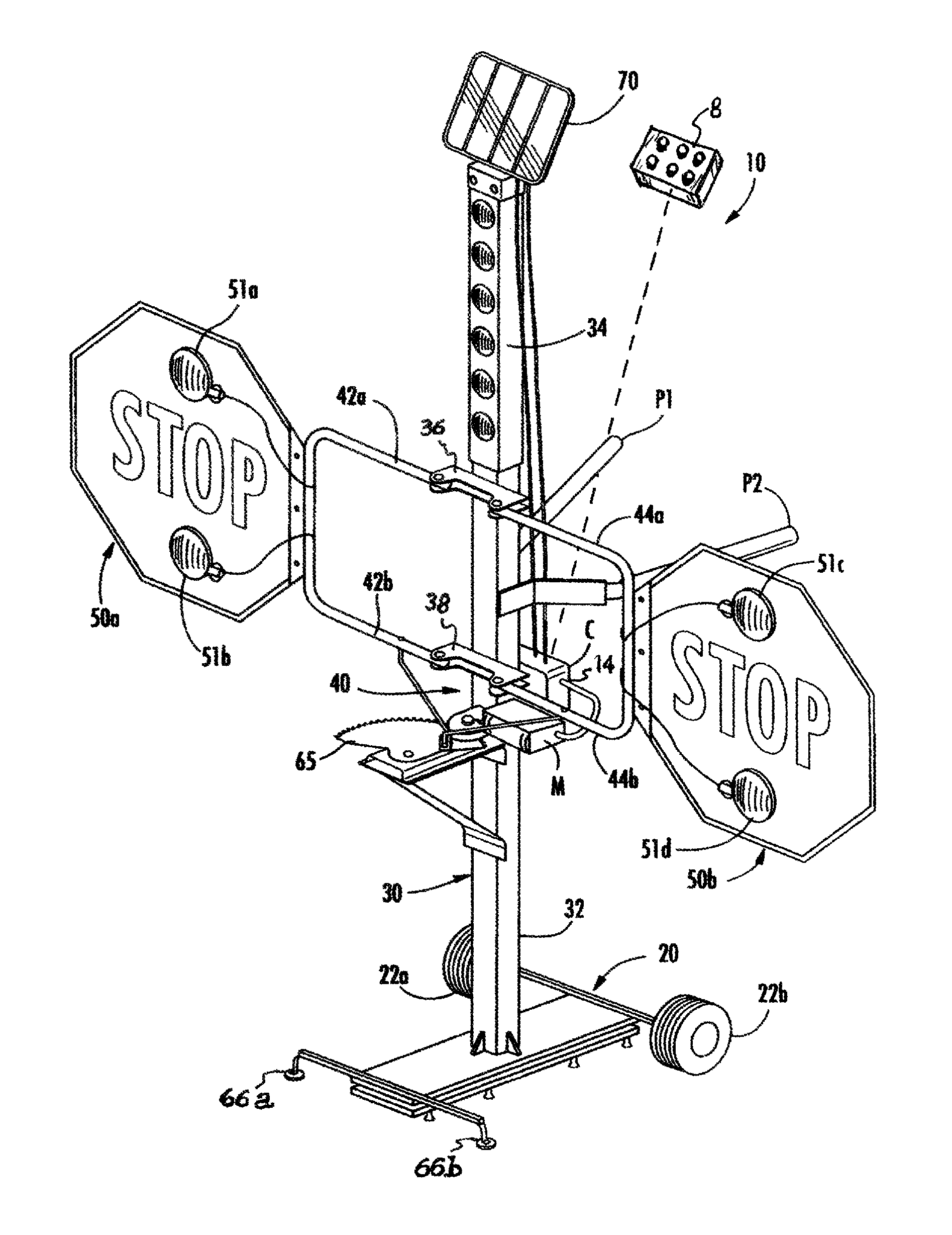
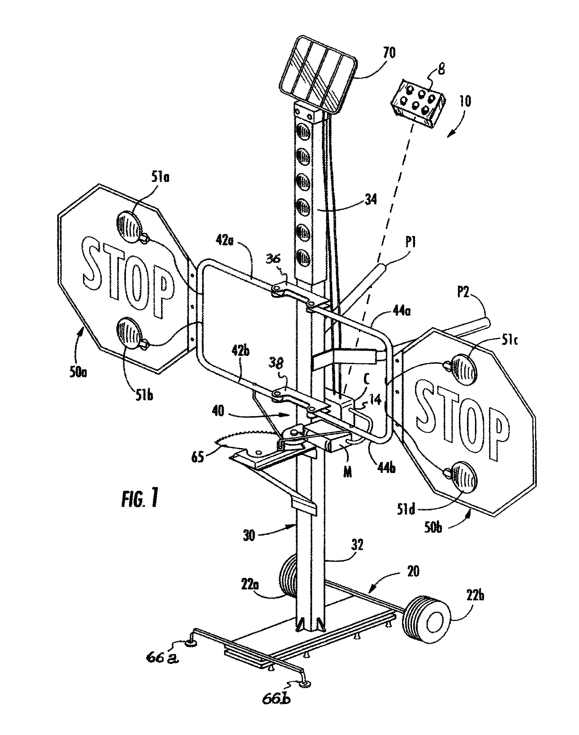
[0055]In FIG. 1 the present invention, referred to herein as freestanding, portable (i.e., easily moved by hand) remote controlled electro-mechanical signal system 10 (or simply, signal system 10), is depicted as including base 20 equipped with at least one wheel 22a, 22b. Signal system 10 structure further comprises a substantially vertical stanchion or tower 30 affixed to said base 20. Tower 30 is structurally defined by a lower portion 32 and upper portion 34. Prominently on said tower 30 upper portion 34 first side (also known as the “display side” and best viewed in FIGS. 1 and 4B), at least one warning light 52 (see also FIGS. 4A and 4B) is disposed so as to form an illuminated upper portion 34. Of course multiple warning lights will likely prove more effective in forming a lighted section of said tower 30 upper portion 34.

[0056]By way of example, a substantially vertical array of warning lights 52a, 52b, 52c, 52d, 52e and 52f may be displayed (SeeFIG. 1, 4A, 4B). Warning ligh...


PUM


Abstract

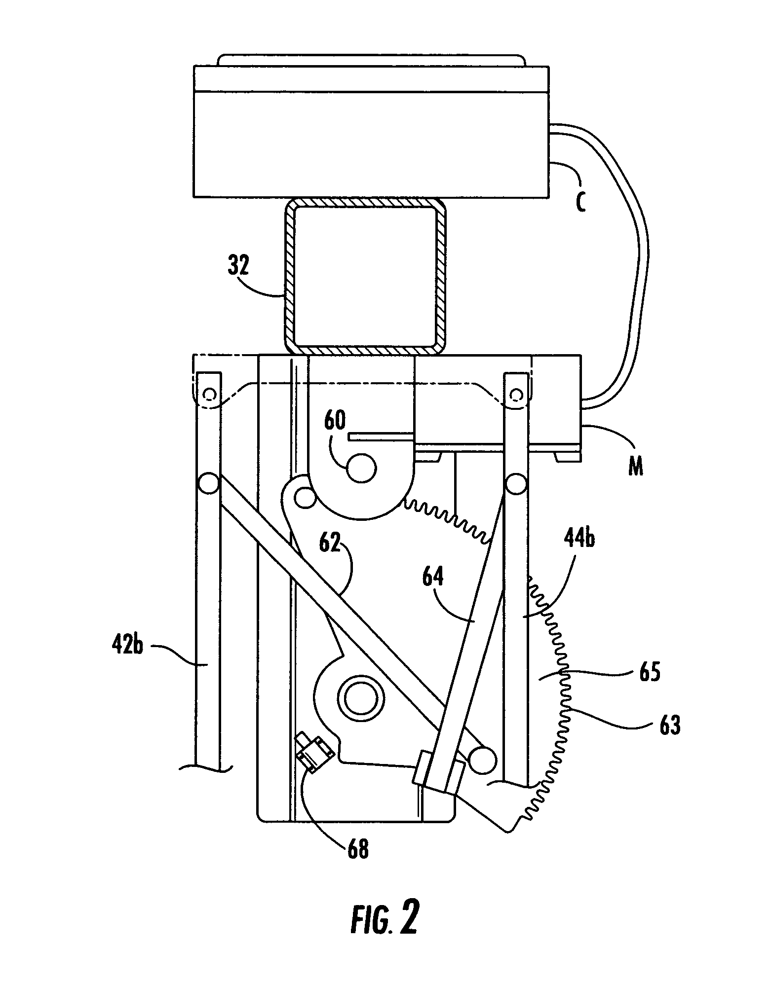
A portable signal system for use by crossing guards, roadway construction flaggers and the like. The signal system is positioned in or alongside a roadway and remotely controllable progressively from an idle or stop mode through a warning stage and ultimately to a traffic stop mode as the signal system frontal profile greatly expands in the face of oncoming motorists. In a warning stage, the signal system presents a flashing amber light array. Following an initial warning period, articulated arms journalled on said signal system and carrying stop signal signs including red lights are swiveled outwardly to stop mode confronting motorists in oncoming traffic. A motor driven gear disk operates through pivoted drive links to control laterally outward and inward movement of the articulated arms carrying the stop signs. The system may be manually moved by handles on wheels to its operational location and anchored in place.

Description

CROSS-REFERENCE TO RELATED APPLICATION[0001]All priority benefits are hereby claimed under 35 USC 119(e) of prior-filed Provisional Patent Application Ser. No. 61 / 344,410 filed Jul. 16, 2010, said provisional patent application in its entirety being incorporated herein by reference thereto and for all purposes, as if fully set forth herein.STATEMENT REGARDING FEDERALLY SPONSORED RESEARCH OR DEVELOPMENT[0002]Not ApplicableNAMES OF THE PARTIES TO A JOINT RESEARCH AGREEMENT[0003]Not ApplicableSEQUENCE LISTING OR COMPUTER PROGRAM LISTING[0004]Not ApplicableBACKGROUND OF THE INVENTION[0005]The present disclosure relates to the management of advancing motorists in roadway traffic. The detailed discussed herein relates generally to temporarily posted signs and signals to warn and stop motorists, and deals more particularly with traffic at or near crosswalks and intersections (such as those patrolled by crossing guards), as well as roadway construction sites (typically involving flaggers). ...

Claims


Application Information

Patent Timeline
Patent Type & Authority Patents(United States)
IPC IPC(8): B60Q7/00
CPCE01F9/681E01F9/677E01F9/615E01F9/646
Inventor PHILLIPS, NATHANIEL
Owner FISHER PHILLIPS VICTORIA C
Learn More