
Refrigerated chest for rapidly quenching beverages and visually identifying when such beverages reach target temperature

a beverage and beverage chest technology, applied in the field of beverages quenching chests, can solve the problems of taking thirty to sixty minutes to cool beverages, user's inability to visually determine, and difficulty in determining whether beverages were sufficiently cooled or even over-cooled, and achieve the effect of rapid quenching or cooling beverages

Inactive Publication Date: 2012-04-24
LAUCHNOR JOHN C
View PDF6 Cites 19 Cited by
  • Summary
  • Abstract
  • Description
  • Claims
  • Application Information

AI Technical Summary

Benefits of technology

[0006]It is therefore an object of the present invention to provide a chest for the rapid cooling or quenching of beverages to a pre-selected temperature through a combination of water quench and refrigeration (preferably within three to ten minutes), and for the indication that the pre-selected temperature of the drink has been achieved.
[0007]It is therefore a further object of the present invention to provide a chest for the rapid quenching of beverages to a pre-selected temperature through a combination of water quench and refrigeration and wherein the successful quenching of the beverages to a pre-selected temperature is indicated to the user.
[0009]It is therefore a still further object of the present invention to provide a chest for the rapid quenching of beverages wherein the pre-selected temperature is maintained for a period of time.
[0010]It is therefore a final object of the present invention to provide a level of elegance and luxury sought by many of today's consumers.

Problems solved by technology

However, the simple use of ice and water for these purposes has been problematic in that it can take thirty to sixty minutes to cool the beverages and the user has no way of visually determining when the drinks are cooled to the ideal temperature.
In short, it has been difficult to determine if the beverages were sufficiently cooled or even over-cooled, and further difficult to maintain the optimum temperature for prolonged periods after the optimum temperature has been achieved.
Additionally, traditional ice chests have typically not provided the level of elegance and luxury sought by many of today's consumers.

Method used


Image

  • Refrigerated chest for rapidly quenching beverages and visually identifying when such beverages reach target temperature
  • Refrigerated chest for rapidly quenching beverages and visually identifying when such beverages reach target temperature
  • Refrigerated chest for rapidly quenching beverages and visually identifying when such beverages reach target temperature

Examples


Embodiment Construction

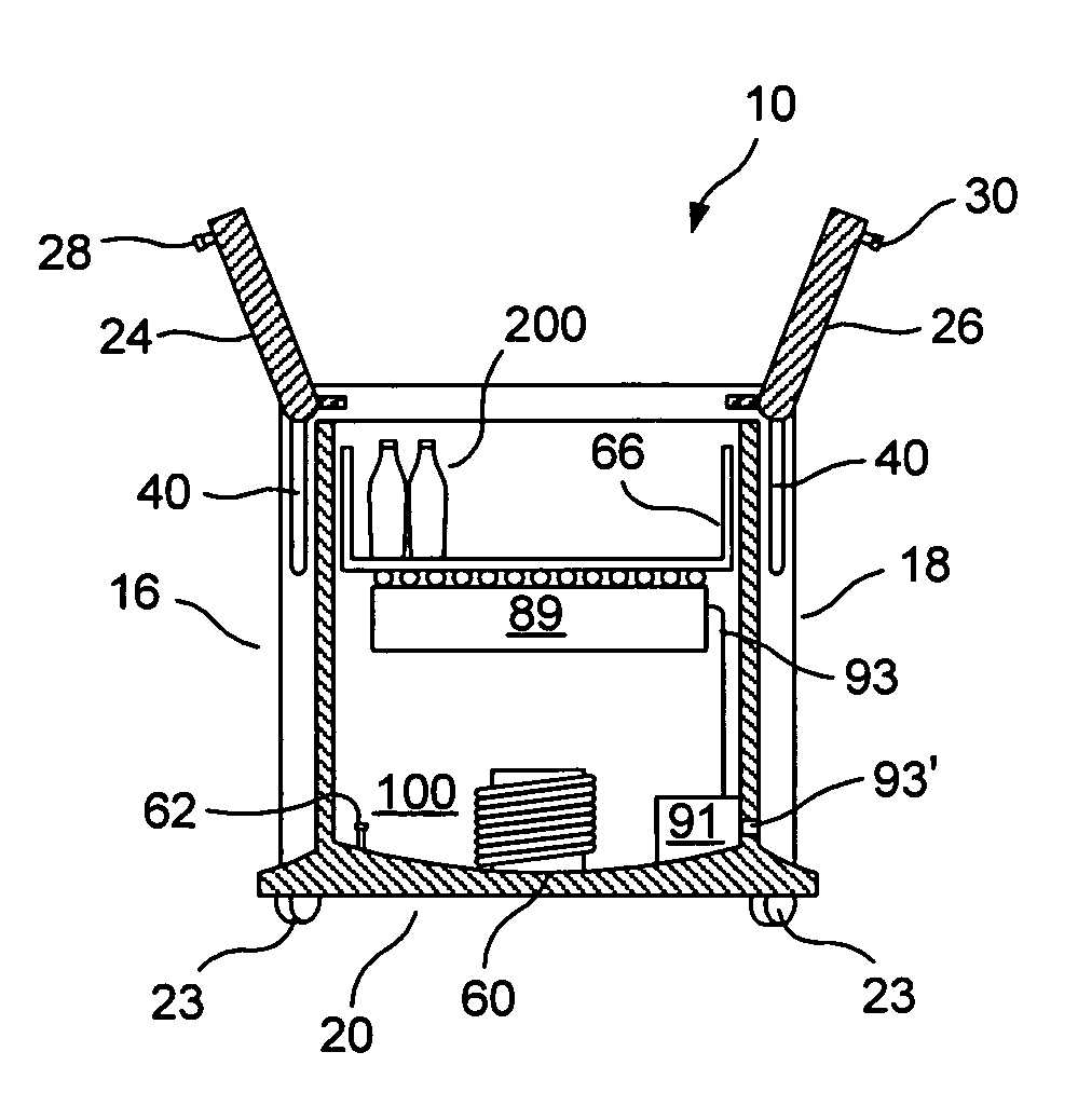
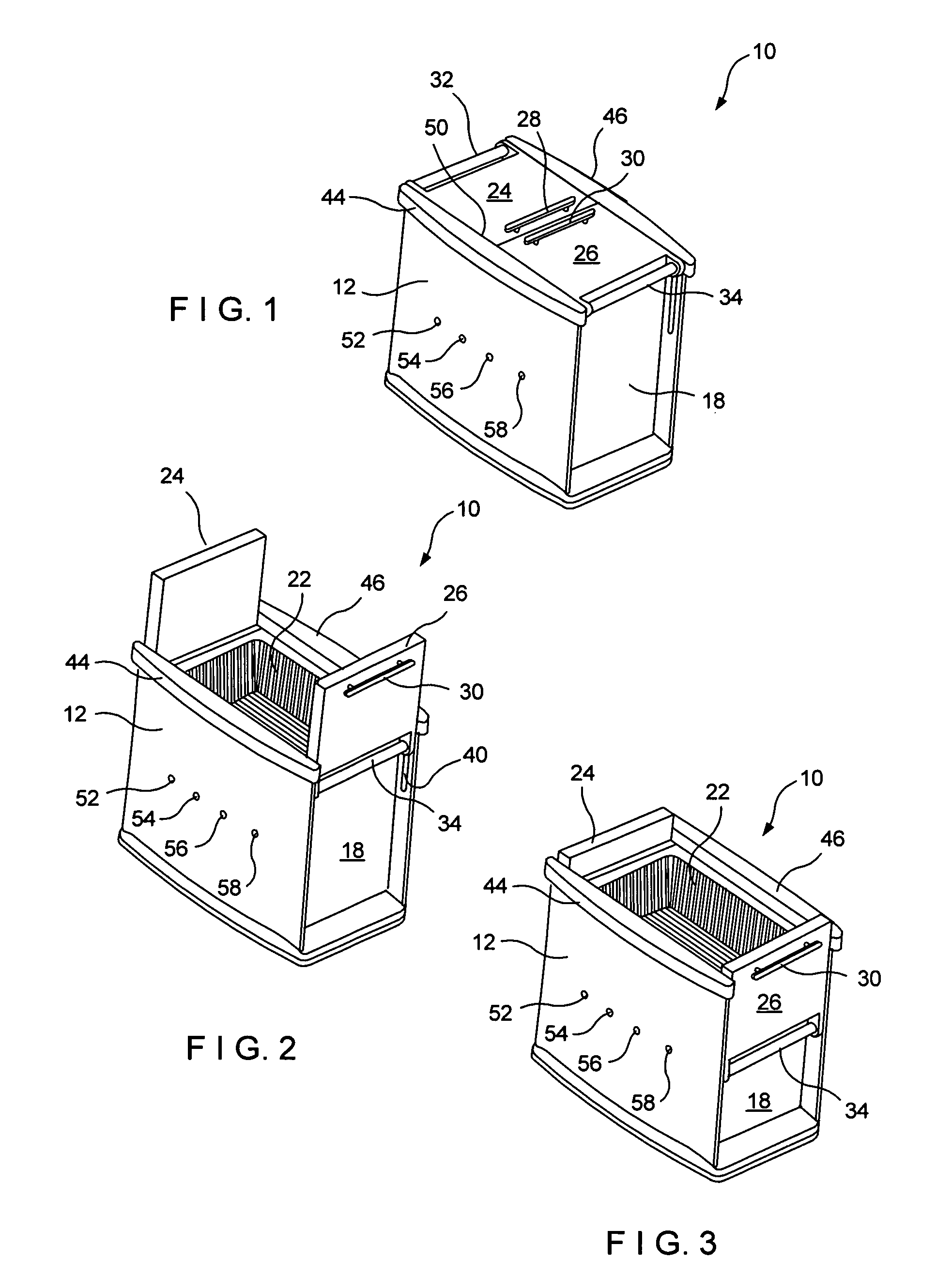
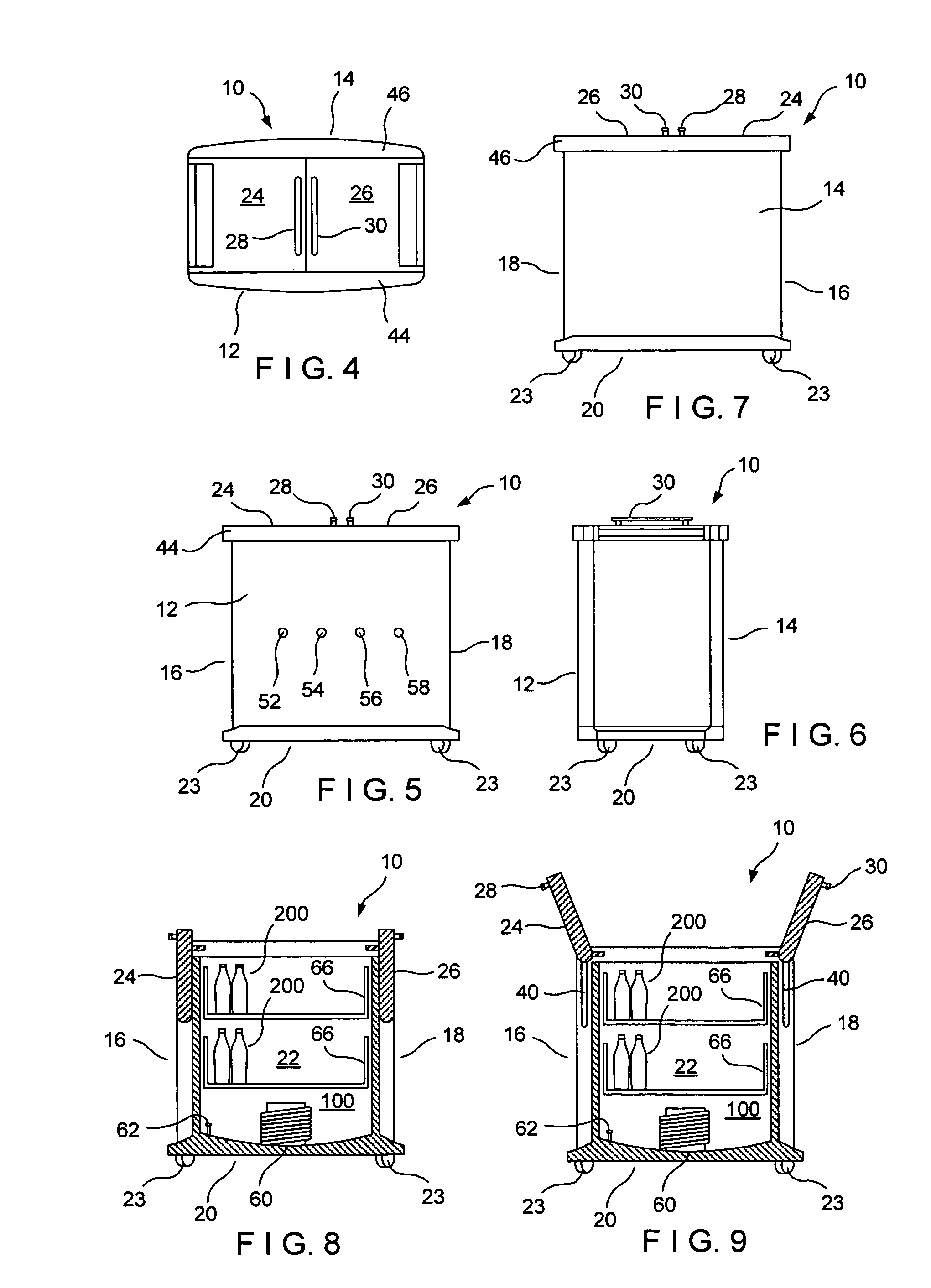
[0028]Referring now to the drawings in detail wherein like numerals indicate like elements throughout the several view, one sees from the various drawings that the chest 10 includes a front wall 12, a rear wall 14, side walls 16, 18 and a bottom wall 20, all in relatively fixed locations thereby forming an interior cooling volume 22. Bottom wall 20 includes wheels 23 at the four corners thereof. Additionally, the illustrated embodiment includes dual top lids or access doors 24, 26 which include respective access door handles 28, 30. Access doors 24, 26 can be in the closed position as shown in FIG. 1 to aid in maintaining the temperature within interior cooling volume 22. Access doors 24, 26 include pivot bars 32, 34 which are further engaged within inwardly facing linear tracks 40 formed in the interior of the lateral edges of the front and rear walls 12, 14, immediately outwardly adjacent of side walls 16, 18 (see FIGS. 2 and 9) thereby allowing the access doors 24, 26 to be initi...


PUM


Abstract

The cooling chest for rapidly quenching beverages includes a quench tray for holding containers of beverage. The quench tray is lowered into salt-water or other cooling liquid which is cooled by a refrigeration unit. A processing device determines the temperature of the beverages within the containers within the quench tray and further activates a mechanism for removing the quench tray from the water or cooling liquid when the desired temperature is reached. The processing device can also activate the mechanism for removing the quench tray from the water or cooling liquid when the upper lid or access doors are opened.

Description

BACKGROUND OF THE INVENTION[0001]1. Field of the Invention[0002]The present invention relates to a refrigerated chest for the quenching of beverages, particularly the rapid quenching of beverages to a pre-selected temperature and visual notification of when beverages are quenched to a certain temperature (i.e., ready to consume).[0003]2. Description of the Prior Art[0004]The use of traditional ice chests for cooling of beverages and maintaining the cooled temperature is well known in the prior art. However, the simple use of ice and water for these purposes has been problematic in that it can take thirty to sixty minutes to cool the beverages and the user has no way of visually determining when the drinks are cooled to the ideal temperature. In short, it has been difficult to determine if the beverages were sufficiently cooled or even over-cooled, and further difficult to maintain the optimum temperature for prolonged periods after the optimum temperature has been achieved.[0005]Add...

Claims


Application Information

Patent Timeline
Patent Type & Authority Patents(United States)
IPC IPC(8): F25D3/08F25D17/02F25D25/00
CPCF25D25/02F25D31/007F25D25/04F25D2400/10F25D2400/28F25D2400/361F25D2400/38F25D2700/02F25D2700/12F25D2700/16
Inventor LAUCHNOR, JOHN C.
Owner LAUCHNOR JOHN C
Learn More