
System and method for detecting facial gestures for control of an electronic device

a technology of facial features and electronic devices, applied in static indicating devices, instruments, colour separation/tonal correction, etc., can solve the problems of other conditions not being able to effectively operate a device such as a mouse with their hands, not being fine-tuned to a particular type of facial gesture, and spinal cord injury level

Active Publication Date: 2012-04-17
VORTANT TECH
View PDF6 Cites 60 Cited by
  • Summary
  • Abstract
  • Description
  • Claims
  • Application Information

AI Technical Summary

Benefits of technology

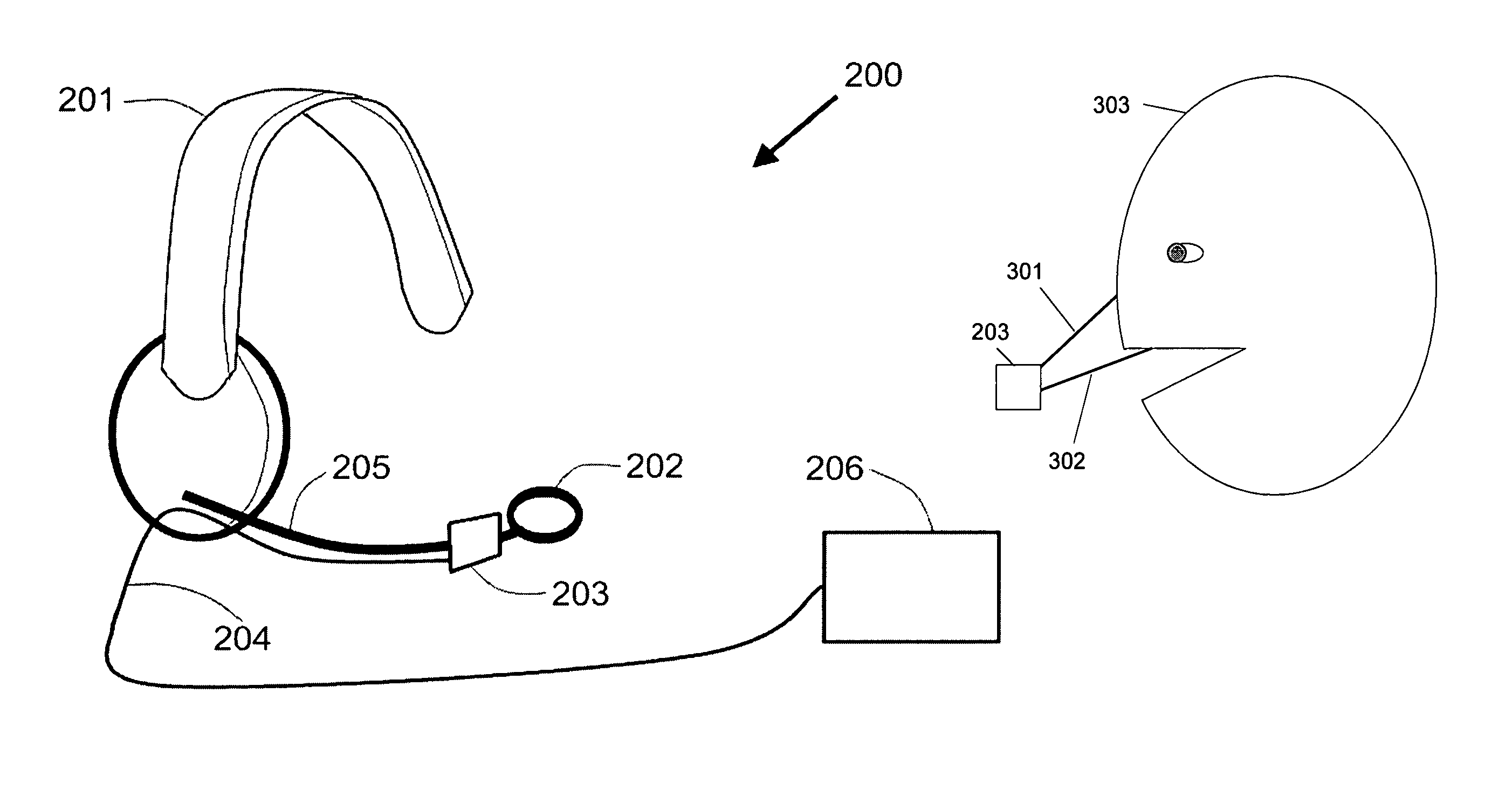
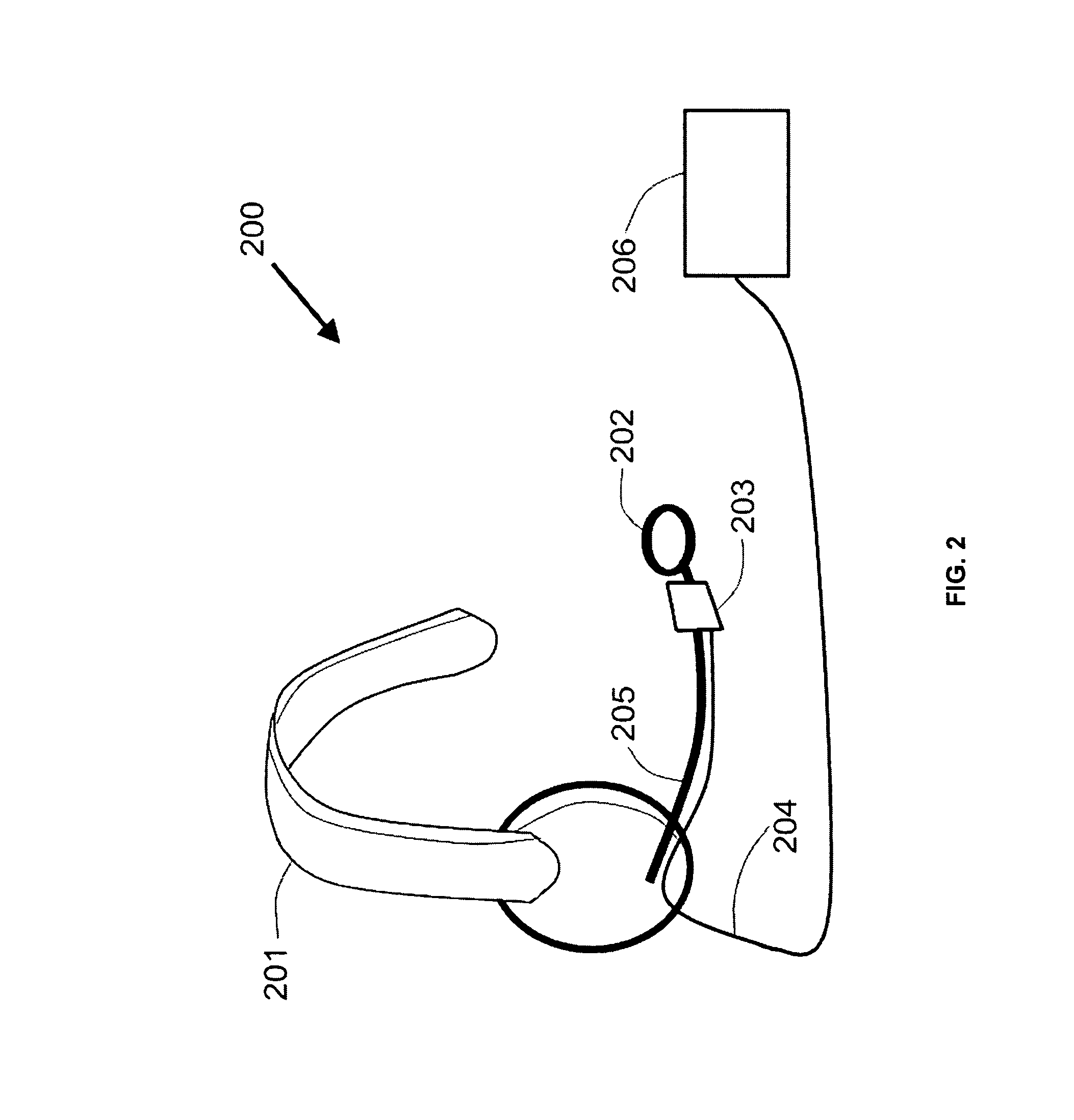
[0021]In another embodiment of the invention, infrared devices are mounted on an eyeglass frame and categorize the movements of the user's eyes. A major advantage of the present invention in this context is that intelligence in the system allows it to measure only approximate eye motion, rather than requiring the high precision of the existing art. In another embodiment of the invention, optical context analysis provides an additional input to differentiate between intentional eye gestures and eye gestures associated with the user scanning new visual information.
[0022]In another embodiment of the invention, the categorization of movements is converted into point and click operations on a computer screen by reducing the number of point and click operations to a small set from which the user can choose. In another embodiment of the invention, the categorization of movements is converted into a selection of items from a menu or list.
[0023]In yet another embodiment of the invention, the categorization of movements is converted into a stream of symbols for interpretation by the electronic device.

Problems solved by technology

For example, individuals with high-level Spinal Cord Injury (SCI), ALS, or other conditions may not be able to effectively operate a device such as a mouse with their hands.
The drawback of these devices is that they tend to be too simple for some uses, and because they are general purpose (i.e., usable for many different types of motions), they are not fine-tuned to a particular type of facial gesture and thus require precise set up and calibration each time they are used.
Since it is only an on / off approach, these devices are not very suitable for pointing input for a device such as a computer, but may be suitable for providing the click input, therefore do not replace all mouse functions.
Additionally, these simple approaches are not well-suited to monitoring gestures from the mouth because they have no way of separating an intentional mouth gesture from a mouth movement naturally made during speech.
However, for some users, moving the head is difficult or leads to discomfort.
However, their drawbacks are in some ways the opposite of the simple optical switches described above—they tend to be complex, expensive, and difficult to use.
However, it is doubtful that this somewhat simpler approach provides sufficient accuracy for use in pointing, as there are many types of nonlinearity in the disclosed system than are caused by the light response of the detectors.
The main technical difficulty that must be overcome for success with eye tracking devices in the art is that great precision is required to be able to move a pointer to the exact place the eye is looking.
If there is any error, the pointer will not be exactly where the user is looking, so it will be very difficult for the user to see the pointer, resulting in the user chasing the pointer around in an attempt to look at it.
Thus, the reason the eye trackers in the prior art tend to be complex and expensive is because they are required to have very high precision to be useful.
On one extreme are eye trackers, which require extreme precision and complexity to provide accurate pointing.

Method used


Image

  • System and method for detecting facial gestures for control of an electronic device
  • System and method for detecting facial gestures for control of an electronic device
  • System and method for detecting facial gestures for control of an electronic device

Examples


Embodiment Construction

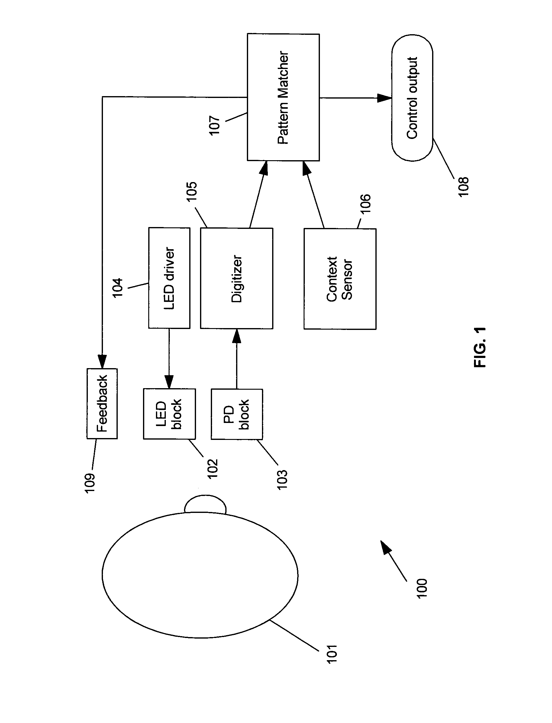
[0035]The availability of low-cost Light-Emitting Diodes (LEDs) and photodetectors (PDs), such as photodiodes and phototransistors, has provided a powerful capability for achieving many kinds of sensing. In the present invention, these components are used in new ways to measure and interpret motions of parts of the user's face, including the eyes. In the description that follows, it will be assumed that LEDs and PDs are used. However, these may be replaced, if desired, with similar results by other light emitting sources and light detecting devices, infrared or otherwise, such as lamps, photosensitive materials, etc.

[0036]As discussed above, many people need to be able to control electronic devices such as computers without the use of their hands, or perhaps in conjunction with the use of their hands. One use for the present invention is for pointing and clicking on objects displayed by a computer. However, there are many other applications of the present invention, such as controll...


PUM

PropertyMeasurementUnit
timeaaaaaaaaaa
time delayaaaaaaaaaa
cut-off frequencyaaaaaaaaaa

Abstract

A control system enables a user to control an electronic device by moving parts of the face, including the eyes. Optical emitters and optical detectors are used to reflect light from the relevant parts of the user's face. Pattern matching or approximation of a pointing location are used to define the control input to the electronic device based on the user's motions. Visual feedback is optionally provided to the user during the controller's actions. Additional sensor elements are optionally provided to improve performance of the system. Hardware and software elements are combined to provide for the specified control actions.

Description

GOVERNMENT LICENSE RIGHTS[0001]This invention was made with United States government support under one or more SBIR grants from the National Institutes of Health. The United States government has certain rights in this invention.CROSS-REFERENCE TO RELATED APPLICATIONS[0002]This patent application claims the benefit of co-pending U.S. Provisional Application No. 60 / 995,796, filed Sep. 27, 2007.FIELD OF INVENTION[0003]This invention relates generally to sensing position and movements of facial features and, more particularly, to a device that uses light to sense the position and motion of a user's face or parts of the face, including mouth or eyes, to provide an interface to an electronic device.BACKGROUND OF THE INVENTION[0004]The Microsoft® Windows and Macintosh® operating systems have revolutionized computer usability for many people by providing a visually-oriented computer screen that can be accessed by pointing and clicking at the objects on the screen. This graphical, window-ba...

Claims


Application Information

Patent Timeline
Patent Type & Authority Patents(United States)
IPC IPC(8): G06K9/00G06K9/46G06F3/033G03F3/10G06V10/145
CPCG06F3/011G02C11/10G06K9/00335G06K9/2036G06F3/013G06V40/20G06V10/145G06V40/18
Inventor SCHAEFER, PHILIP RAYMOND
Owner VORTANT TECH
Learn More