
Liquid crystal drive apparatus and liquid crystal display apparatus

a liquid crystal drive and display device technology, applied in the direction of instruments, computing, electric digital data processing, etc., can solve the problems of picture quality degradation, insufficient speed, picture quality degradation in moving pictures, etc., and achieve the effect of less picture quality degradation and small siz

Inactive Publication Date: 2012-04-17
KK TOSHIBA
View PDF9 Cites 0 Cited by
  • Summary
  • Abstract
  • Description
  • Claims
  • Application Information

AI Technical Summary

Benefits of technology

The present invention aims to provide a liquid crystal drive apparatus and display apparatus that have better picture quality and are smaller in circuit scale. The invention includes a storage unit to store an enhancement correction coefficient, a frame memory to hold digital image information, a computation unit to compute the difference between frames, another computation unit to compute enhancement image information, and a drive signal generation unit to generate a drive signal. The technical effect of the invention is to improve the quality of liquid crystal display and reduce the size of the circuit.

Problems solved by technology

Since the response speed of liquid crystal is not sufficiently fast, however, picture quality degradation such as blur or after image occurs in the liquid crystal display when a moving picture is displayed.
The problem that the response rate between intermediate gray scale levels is not sufficient causes picture quality degradation in moving pictures.
However, the above-described scheme in which the enhancement image information Lα is obtained by referring to the array data has a large number of processing steps.

Method used


Image

  • Liquid crystal drive apparatus and liquid crystal display apparatus
  • Liquid crystal drive apparatus and liquid crystal display apparatus
  • Liquid crystal drive apparatus and liquid crystal display apparatus

Examples


first embodiment

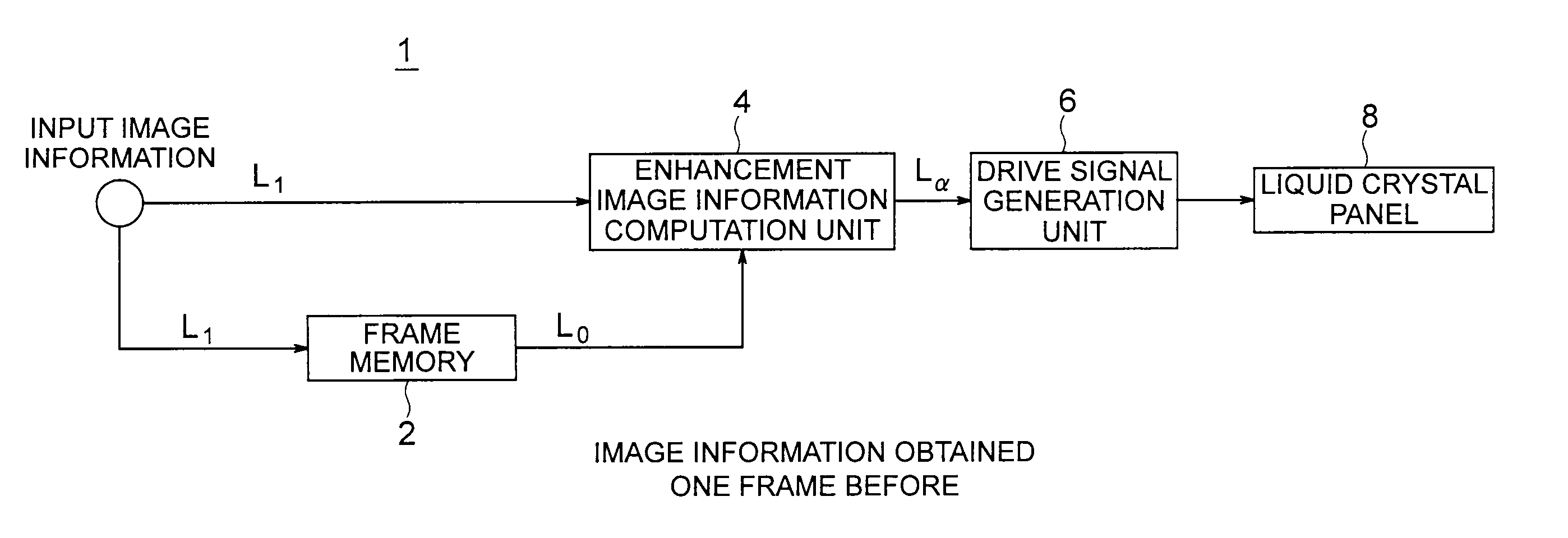
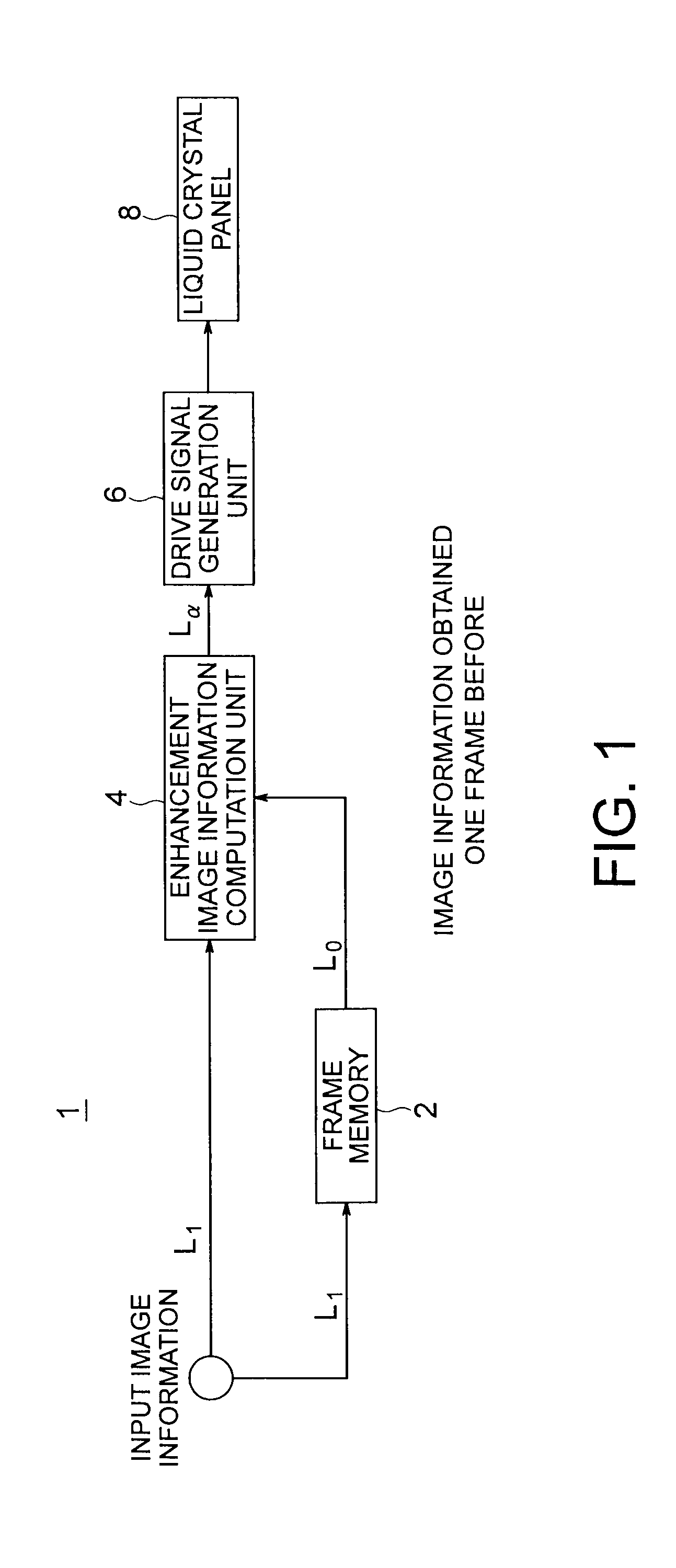
[0044]A liquid crystal display apparatus according to a first embodiment of the present invention is shown in FIG. 1. The liquid crystal display apparatus 1 according to the present embodiment includes a frame memory 2 which holds gray scale levels L1 respectively of color signals (for example, color signals of R (red), G (green) and B (blue)) corresponding to one frame of an input image signal, an enhancement image information computation unit 4, a drive signal generation unit 6, and a liquid crystal panel 8.

[0045]Gray scale levels (referred to as input image information as well) L1 of respective color signals in the input image signal input to the liquid crystal display apparatus 1 are sent to the frame memory 2 and stored therein, and sent to the enhancement image information computation unit 4. The enhancement image information computation unit 4 computes enhancement image information Lα on the basis of the gray scale levels L1 of the input image signal and gray scale levels (re...

second embodiment

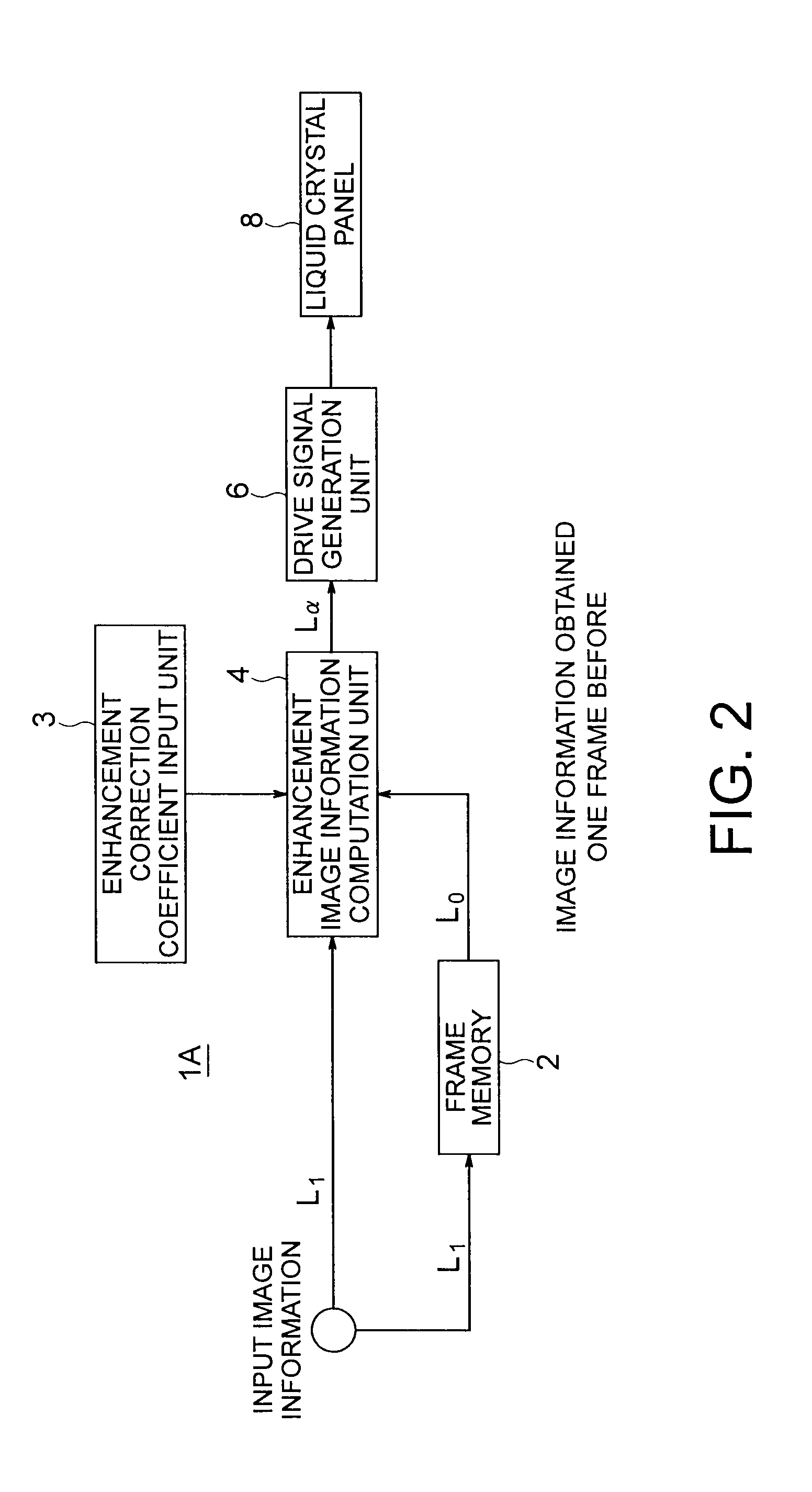
[0056]A liquid crystal display apparatus according to a second embodiment of the present invention is shown in FIG. 2. A liquid crystal display apparatus 1A according to the present embodiment has a configuration obtained by providing an enhancement correction coefficient input unit 3 in the liquid crystal display apparatus 1 according to the first embodiment shown in FIG. 1. The user can input the enhancement correction coefficient via the enhancement correction coefficient input unit 3. A plurality of enhancement correction coefficients are set in the enhancement correction coefficient input unit 3. It is also possible for the user to select one from these enhancement correction coefficients, and the user may newly set an enhancement correction coefficient. The enhancement correction coefficient input unit 3 serves as an interface which makes it possible for the user to select or set an enhancement correction coefficient. The enhancement correction coefficient which can be selecte...

third embodiment

[0060]A liquid crystal display apparatus according to a third embodiment of the present invention will now be described.

[0061]Relations between the enhancement image information Lα and the input image information L1 in the liquid crystal display apparatus according to the first embodiment are measured by using the delayed image information L0 as a parameter. Results of the measurement are shown in FIG. 4. This measurement is conducted by changing the delayed image information L0 from gray scale level 0 to gray scale level 256 at intervals of 16 gray scale levels.

[0062]As L0 changes from gray scale level 0 to gray scale level 256, the graph indicating the relations between the enhancement image information Lα and the input image information L1 gradually changes from the left to the right. Graphs obtained by plotting the measurement results with (Lα−L0) taken on the ordinate axis and (L1−L0) taken on the abscissa axis are shown in FIG. 5. As appreciated from FIG. 5, (Lα−L0) and (L1−L0...


PUM


Abstract

A liquid crystal drive apparatus includes: a storage unit storing an enhancement correction coefficient having (1 / 2n)×m below a decimal point where n is 3 or 4, and m is an integer which is at least 0 and less than 2n; a frame memory holding digital image information of a second frame located one frame before a first frame; a first computation unit computing a difference between digital image information of the first frame and digital image information of the second frame; a second computation unit computing enhancement image information for conducting enhancement display of an image on a liquid crystal panel on the basis of the difference and the enhancement correction coefficient; a third computation unit computing addition information by adding the digital image information of the second frame to the enhancement image information; and a drive signal generation unit generating a drive signal on the basis of the addition information to drive the liquid crystal panel.

Description

CROSS-REFERENCE TO RELATED APPLICATION[0001]This application is based upon and claims the benefit of priority from prior Japanese Patent Application No. 2007-221031 filed on Aug. 28, 2007 in Japan, the entire contents of which are incorporated herein by reference.BACKGROUND OF THE INVENTION[0002]1. Field of the Invention[0003]The present invention relates to a liquid crystal drive apparatus and a liquid crystal display apparatus.[0004]2. Related Art[0005]In recent years, the liquid crystal display has spread in wide fields such as personal computer monitors, notebook computers and television sets. In keeping with this, opportunities to watch moving pictures on liquid crystal displays are increasing intensively. Since the response speed of liquid crystal is not sufficiently fast, however, picture quality degradation such as blur or after image occurs in the liquid crystal display when a moving picture is displayed. In general, since the refresh rate of the liquid crystal display is 6...

Claims


Application Information

Patent Timeline
Patent Type & Authority Patents(United States)
IPC IPC(8): G09G3/36G09G5/10G09G5/00G06F3/038
CPCG09G3/3648G09G2320/0252G09G2320/0261G09G2320/0285G09G2340/16
Inventor HOTTA, AIRAOKUMURA, HARUHIKOMINAMIZAKI, HIRONORISASAKI, HISASHI
Owner KK TOSHIBA
Learn More