
Method and apparatus for DC bus capacitor pre-charge

a technology of dc bus capacitor and pre-charger, which is applied in the direction of power conversion system, ac-ac conversion, and conversion with intermediate conversion to dc, etc. it can solve the problems of dc bus fuse blowing, inverter switch and or load linked to an inverter can be damaged, and the cost of a relay required to short out the resistor can often exceed the additional cost associated with scr switches, and achieves a versatile and inexpensive solution.

Active Publication Date: 2012-04-10
ROCKWELL AUTOMATION TECH
View PDF18 Cites 15 Cited by
  • Summary
  • Abstract
  • Description
  • Claims
  • Application Information

AI Technical Summary

Benefits of technology

The invention provides a solution for pre-charging the DC bus capacitor in a versatile and cost-effective way. A rectifier bridge with controllable switching devices is used to gradually increase the voltage of the DC bus capacitor while avoiding a large startup current. The controllable devices can be silicon controlled rectifiers (SCRs) that are controlled to be full on when associated phase voltages are positive. A high frequency pulse generator is used to generate firing pulses for the SCRs without the need for tracking the phase angles of voltages associated with them. The invention allows for a controlled and gradual increase in voltage, reducing the risk of damage to the DC bus capacitor and ensuring a reliable and efficient power conversion system.

Problems solved by technology

As known in the power conversion industry, the inverter switches and or a load linked to an inverter can be damaged if they are exposed to excessive currents.
When power is initially applied to a converter upon start up, if the DC bus capacitor is uncharged, capacitor appears as a short circuit at the DC bus and therefore, if the three phase AC power is immediately applied to the DC bus, excessive currents can cause the DC bus fuses to blow.
The SCR solution works well in large drives where the cost of a relay required to short out the resistor can often exceed the additional costs associated with the SCR switches and a switch controller.

Method used


Image

  • Method and apparatus for DC bus capacitor pre-charge
  • Method and apparatus for DC bus capacitor pre-charge
  • Method and apparatus for DC bus capacitor pre-charge

Examples


Embodiment Construction

[0018]One or more specific embodiments of the present invention will be described below. It should be appreciated that in the development of any such actual implementation, as in any engineering or design project, numerous implementation-specific decisions must be made to achieve the developer's specific goals, such as compliance with system-related and business related constraints, which may vary from one implementation to another. Moreover, it should be appreciated that such a development effort might be complex and time consuming, but would nevertheless be a routine undertaking of design, fabrication, and manufacture for those of ordinary skill having the benefit of this disclosure.

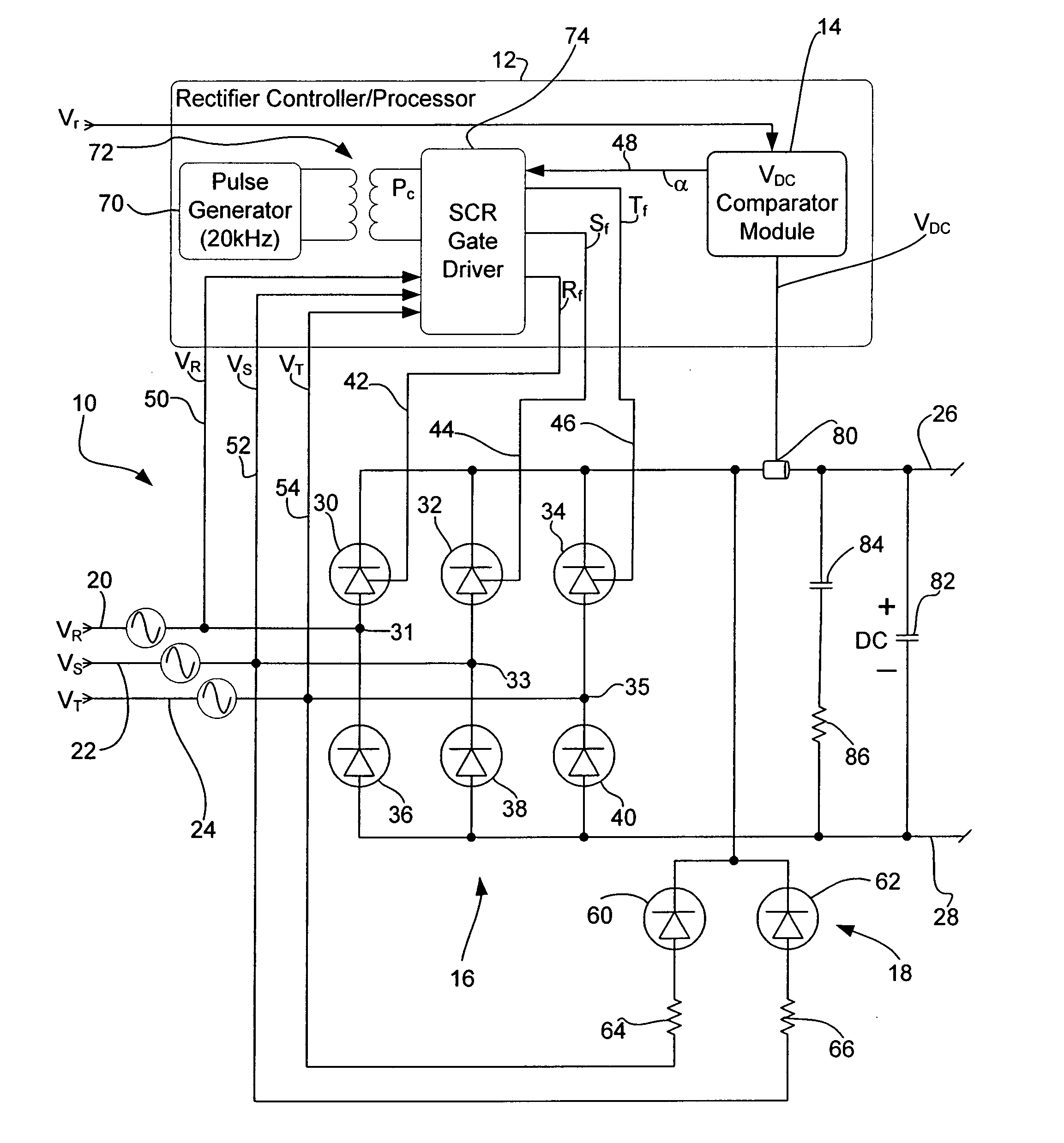
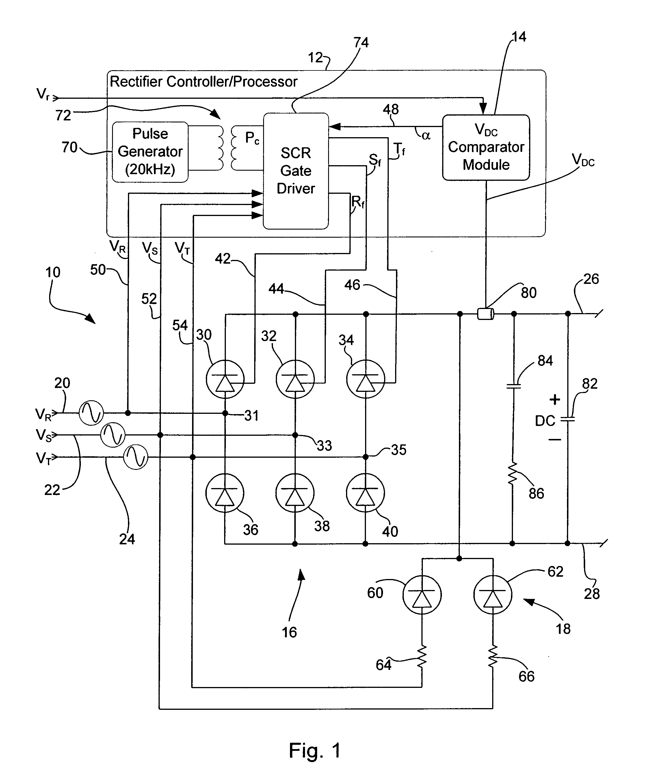
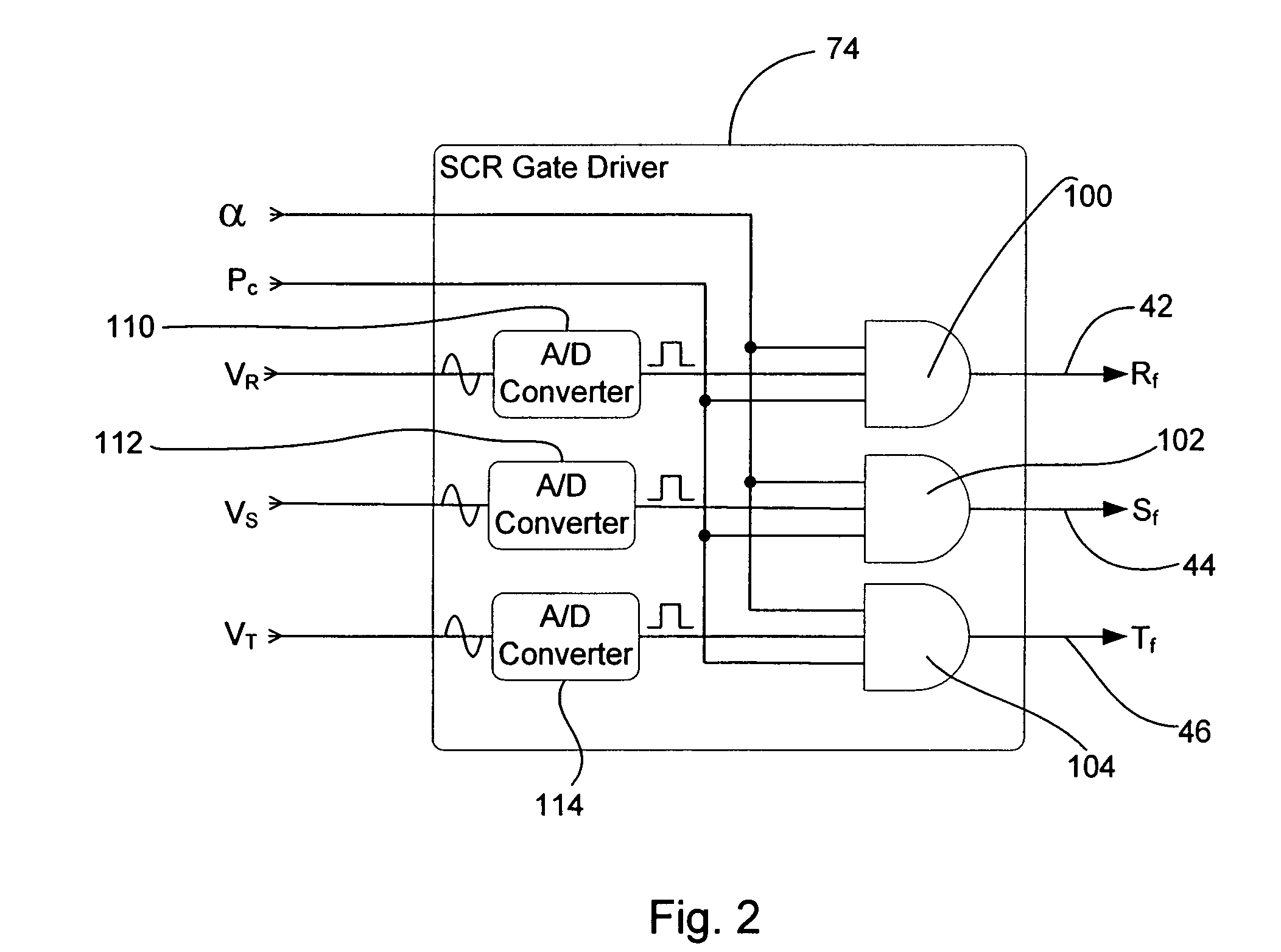
[0019]Referring now to the drawings wherein like reference numerals correspond to similar elements throughout the several views and, more specifically, referring to FIG. 1, the present invention will be described in the context of an exemplary rectifier and control system 10 including, among other comp...


PUM


Abstract

A method and apparatus for converting three phase AC voltages on first, second and third input lines to DC voltage across positive and negative DC buses, the apparatus comprising a rectifier including first, second and third rectifier legs, each leg including a switch and a diode wherein the switch is linked between the positive DC bus and an cathode of the diode, an anode of the diode is linked to the negative DC rail and the first, second and third diode cathodes are linked to the first, second and third input lines, respectively, a DC bus voltage sensor linked to the positive DC bus and measuring the DC bus voltage to generate a measured DC bus voltage and a rectifier controller that receives the measured DC bus voltage, a reference voltage value and the three phase AC voltages wherein, when the measured DC bus voltage is at least equal to the reference voltage value, the controller turns on the switches in the first, second and third rectifier legs when the voltages on the first, second and third input lines are positive, respectively.

Description

CROSS-REFERENCE TO RELATED APPLICATIONS[0001]Not applicable.STATEMENT REGARDING FEDERALLY SPONSORED RESEARCH OR DEVELOPMENT[0002]Not applicable.BACKGROUND OF THE INVENTION[0003]This invention relates to DC bus capacitor pre-charging systems and more specifically to a method and apparatus for use in controlling rectification of three phase AC supply voltages to allow pre-charging of a DC bus capacitor prior to full rectifier activity.[0004]A typical power converter includes a rectifier stage and an inverter stage wherein the rectifier stage is provided between three phase AC power lines and a DC bus and the inverter stage is provided between the DC bus and a load. The rectifier, as the label implies, rectifies the three phase AC voltages to generate a DC voltage across the DC bus. The DC bus typically includes a DC bus capacitor that charges as the rectifier operates. The inverter receives the DC voltage and is controlled to change that DC voltage into three phase AC voltages that ar...

Claims


Application Information

Patent Timeline
Patent Type & Authority Patents(United States)
IPC IPC(8): H02M7/155H02M7/04
CPCH02M1/36H02M7/1626
Inventor GILMORE, THOMAS PATRICK
Owner ROCKWELL AUTOMATION TECH
Learn More