
Apparatus for carrying out DNP-NMR measurements with a compensation configuration and method for designing the compensation configuration

a compensation configuration and apparatus technology, applied in the field of apparatus for carrying out dnpnmr measurements, can solve the problems of not being very sensitive, requiring high-frequency radiation for epr excitation, and being technically difficult, so as to reduce the distance between the first and the second working volume, reduce the loss of pre-polarization of the sample, and shorten the transfer time

Active Publication Date: 2012-04-10
BRUKER SWITZERLAND AG
View PDF14 Cites 11 Cited by
  • Summary
  • Abstract
  • Description
  • Claims
  • Application Information

AI Technical Summary

Benefits of technology

This solution enhances field homogeneity in the second working volume, enabling efficient DNP excitation and sample polarization, while simplifying the design and maintenance of NMR systems by eliminating the need for complex coil configurations and reducing polarization loss during sample transfer.

Problems solved by technology

However, this method has the disadvantage that it is not very sensitive because the polarization of the atomic nuclei is only weak even in large magnetic fields.
The former method has the disadvantage that, because of the typically very large field strength in the NMR working volume, a very high-frequency radiation is required for the EPR excitation, which is technically very difficult.
One essential disadvantage of the configuration according to WO 2005 / 114244 A1 is that a conventional NMR magnet system cannot be upgraded in this manner, meaning that the entire DNP-NMR magnet system has to be developed anew.
Moreover, the mutual influence of the two magnets is also problematic.
All these conditions can lead to complicated coil configurations.

Method used


Image

  • Apparatus for carrying out DNP-NMR measurements with a compensation configuration and method for designing the compensation configuration
  • Apparatus for carrying out DNP-NMR measurements with a compensation configuration and method for designing the compensation configuration
  • Apparatus for carrying out DNP-NMR measurements with a compensation configuration and method for designing the compensation configuration

Examples


Embodiment Construction

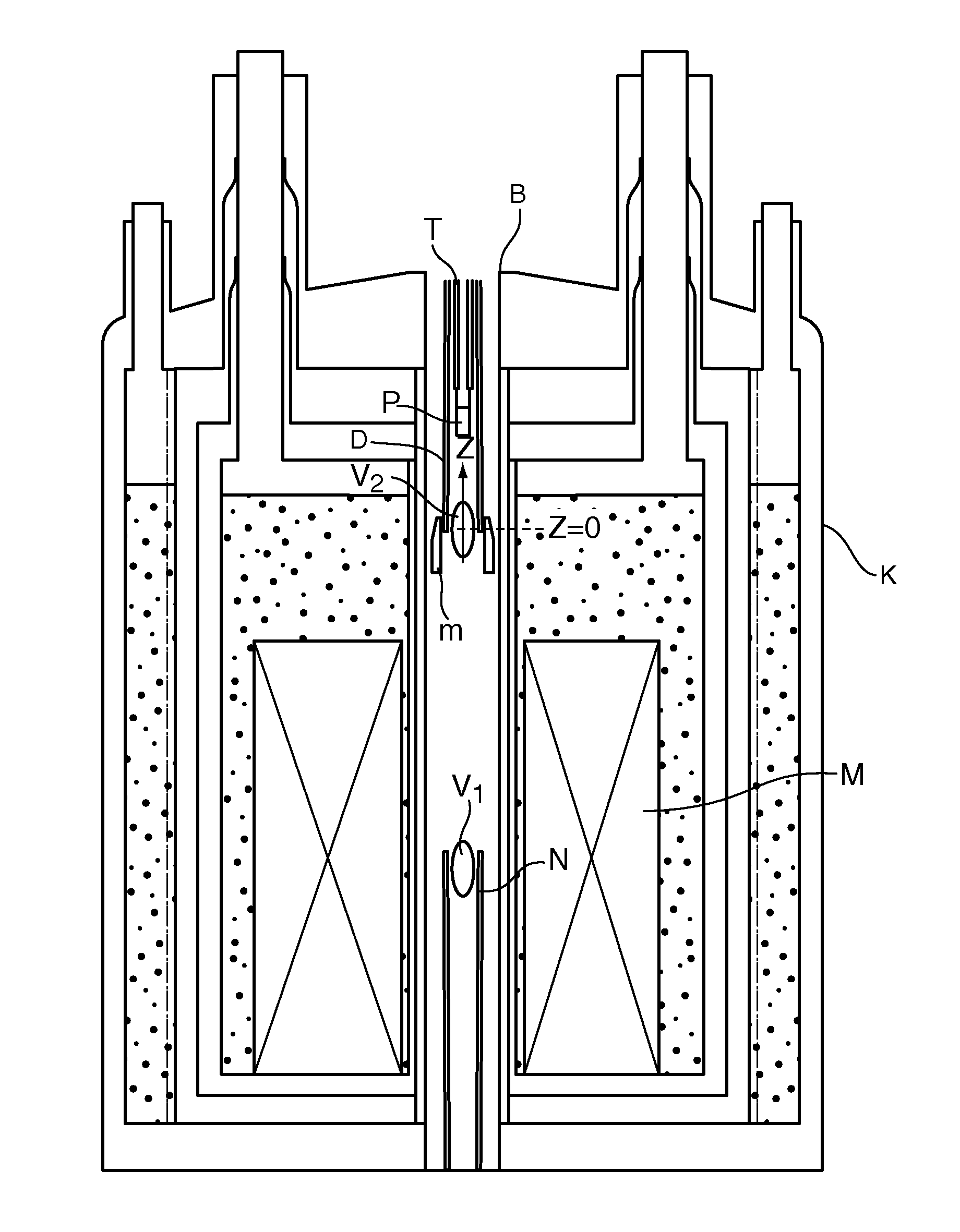
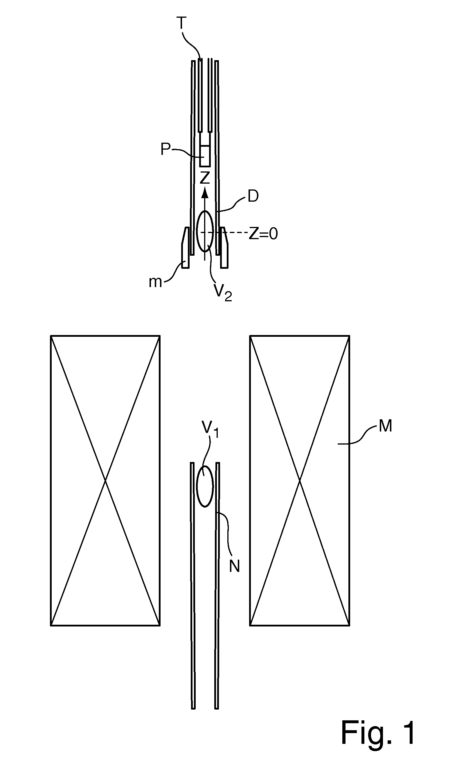
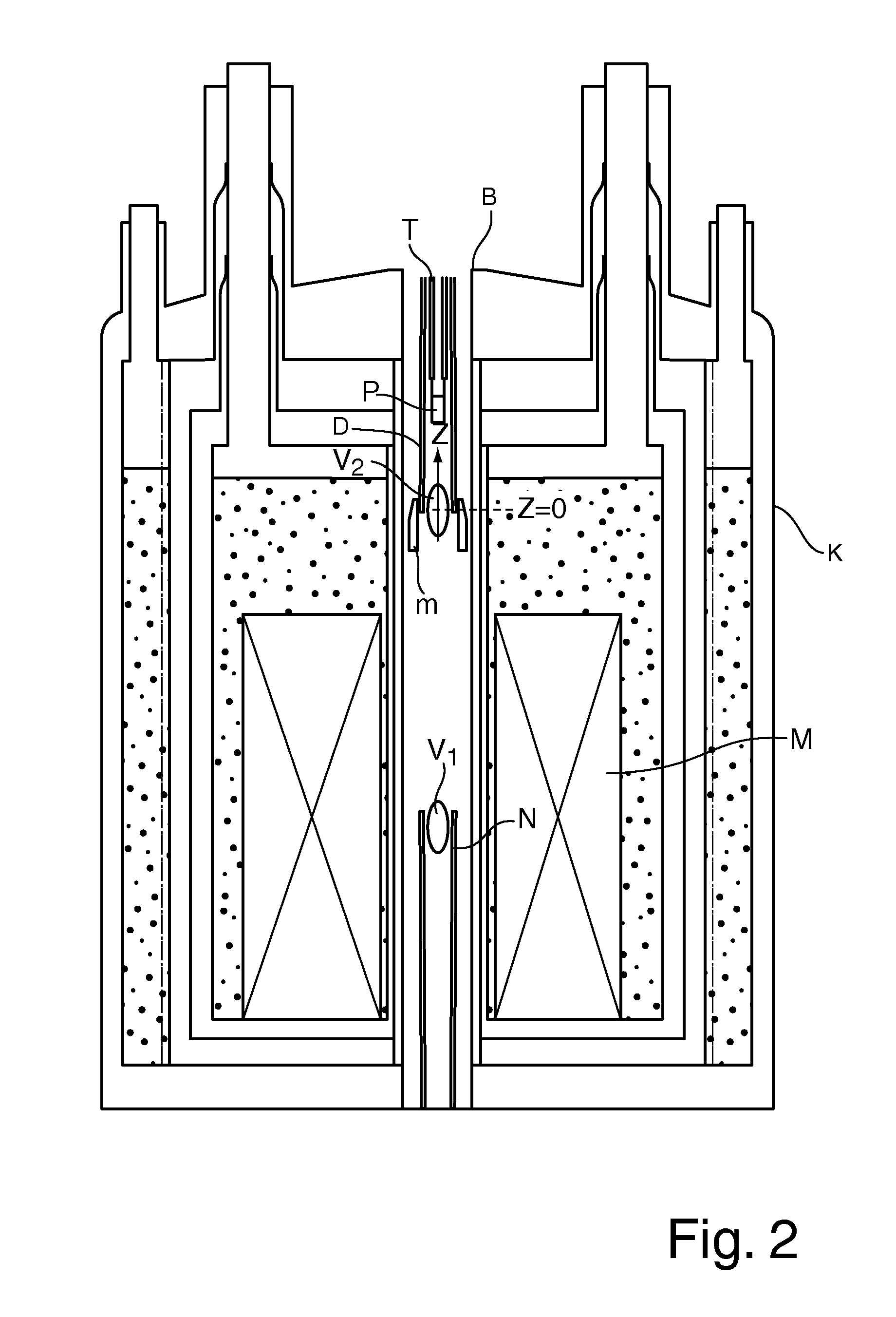
[0044]FIG. 1 shows an apparatus for DNP-NMR measurement of a sample P. The NMR measurement is performed in the first working volume V1 that is surrounded by a magnet configuration M. The magnet configuration M produces a homogeneous magnetic field (H0 field) in the first working volume V1 and, in the second working volume V2, a stray field in the direction of an axis (z-axis) with a magnetic field gradient H1M and / or with field gradients of higher orders (H2M, H3M, . . . ) in this direction. A device N for NMR measurement (probehead) is disposed around the first working volume V1. The sample P can be moved between the first working volume V1 and the second working volume V2 by means of a transporting mechanism T. Near the second working volume V2, a compensation configuration m made of magnetic material and a device D for DNP excitation is mounted. The compensation configuration m is disposed in a limited axial region around the z-axis. In this case, the compensation configuration m...


PUM


Abstract

An apparatus for DNP-NMR measurement on a sample, with a magnet configuration for producing a magnetic field in a first working volume and in, a second working volume with a magnetic field gradient in the direction of an axis (z) which extends through the second working volume, with a device for measuring MR signals, with a DNP excitation device, and with a positioning mechanism for transferring the sample, is characterized in that, near the second working volume, a compensation configuration made of magnetic material is mounted that, in the operating condition of the magnet configuration, produces a magnetic field gradient in the direction of the axis (z) in the second working volume that is between −90% and −110% of the magnetic field gradient of the same order of the stray field of the magnet configuration.

Description

[0001]This application claims Paris Convention priority of DE 10 2008 033 886.9 filed Jul. 18, 2008 the complete disclosure of which is hereby incorporated by reference.BACKGROUND OF THE INVENTION[0002]The invention relates to an apparatus for carrying out DNP-NMR measurements on a sample, with a magnet configuration for producing a magnetic field in a first working volume, wherein the magnet configuration produces a stray field in a second working volume in the direction of an axis with at least one magnetic field gradient of first or higher order in the direction of the axis, wherein the axis extends through the second working volume, with a device for measurement of magnetic resonance (MR) signals of the sample from the first working volume, with a DNP excitation device for DNP excitation of the sample in the second working volume, and with a positioning mechanism for transferring the sample between the second working volume and the first working volume.[0003]Such a configuration...

Claims


Application Information

Patent Timeline
Patent Type & Authority Patents(United States)
IPC IPC(8): G01V3/00
CPCG01R33/30G01R33/3873G01R33/62G01R33/281G01R33/3875
Inventor BOVIER, PIERRE-ALAINSCHAUWECKER, ROBERTECKERT, DANIEL
Owner BRUKER SWITZERLAND AG
Learn More