
Centrifugal rotary blood pump with impeller having a hydrodynamic thrust bearing surface

a centrifugal rotary, blood pump technology, applied in the direction of piston pumps, positive displacement liquid engines, prosthesis, etc., can solve the problems of mechanical wear, premature wear, thrombosis and sometimes hemolysis of mechanical pumps, etc., and achieve the effect of creating radial impeller stiffness

Active Publication Date: 2012-04-10
HEARTWARE INC
View PDF33 Cites 146 Cited by
  • Summary
  • Abstract
  • Description
  • Claims
  • Application Information

AI Technical Summary

Benefits of technology

The patent describes a rotary blood pump that includes a housing with a pumping chamber defined by the housing's exterior surfaces. The pump includes one or more electromagnetic motor stators outside the pumping chamber. The pump includes a rotatable impeller with a hydrodynamic thrust bearing surface that is adapted to constrain the impeller's position relative to the housing without the need for a constant polar magnetic force. The pump is designed to improve blood flow characteristics and can be implanted within the pericardial space of a patient. The technical effects of the invention include improved blood flow, reduced pump size, and reduced energy consumption.

Problems solved by technology

Such mechanical pumps are normally large and prone to mechanical wear.
This too became a source of thrombosis and sometimes hemolysis, as well as premature wear.

Method used


Image

  • Centrifugal rotary blood pump with impeller having a hydrodynamic thrust bearing surface
  • Centrifugal rotary blood pump with impeller having a hydrodynamic thrust bearing surface
  • Centrifugal rotary blood pump with impeller having a hydrodynamic thrust bearing surface

Examples


Embodiment Construction

[0051]In describing the embodiments of the present invention illustrated in the drawings, specific terminology is employed for sake of clarity. However, the present disclosure is not intended to be limited to the specific terminology so selected, and it is to be understood that each specific element includes all technical equivalents that operate in a similar manner.

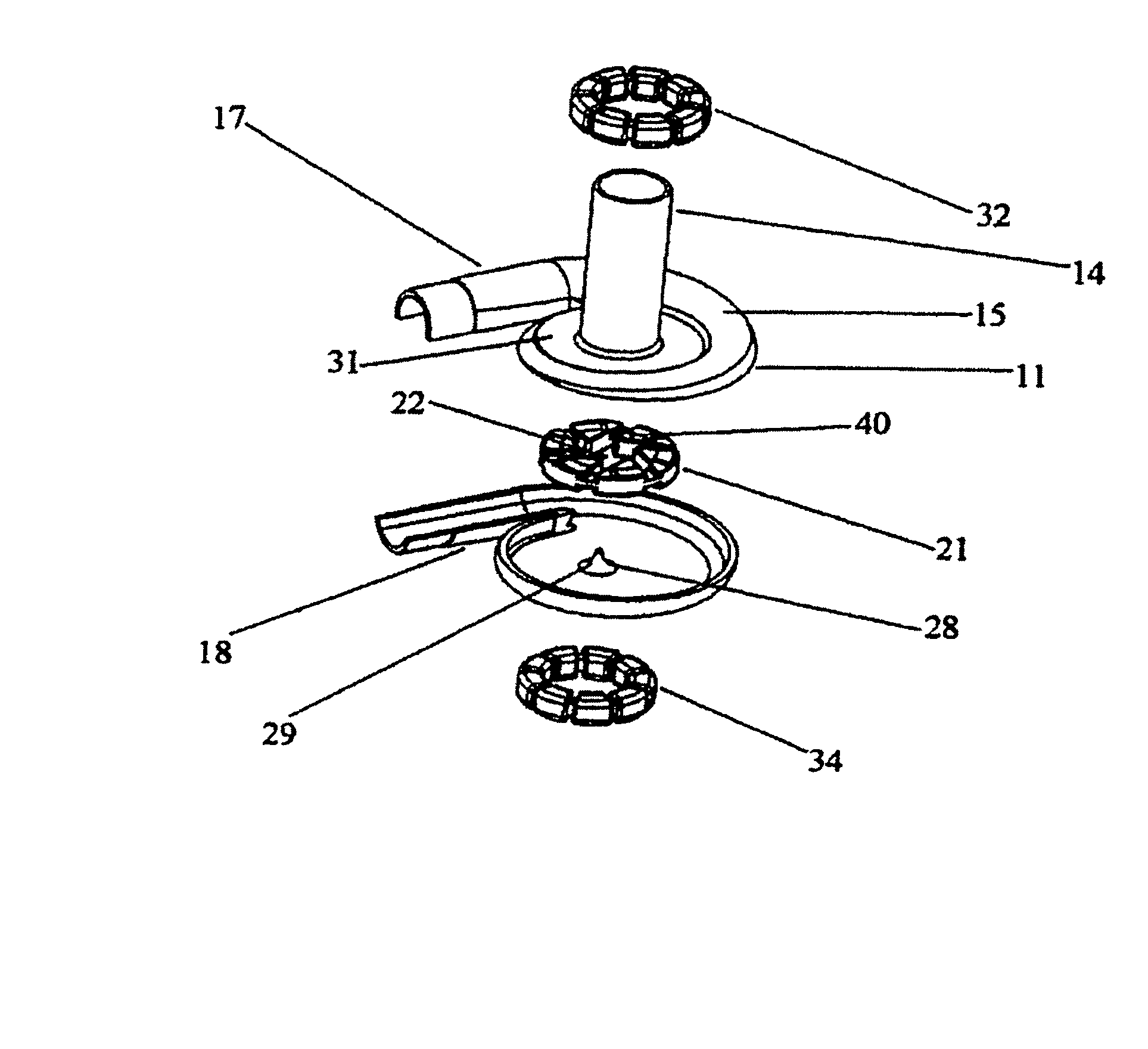
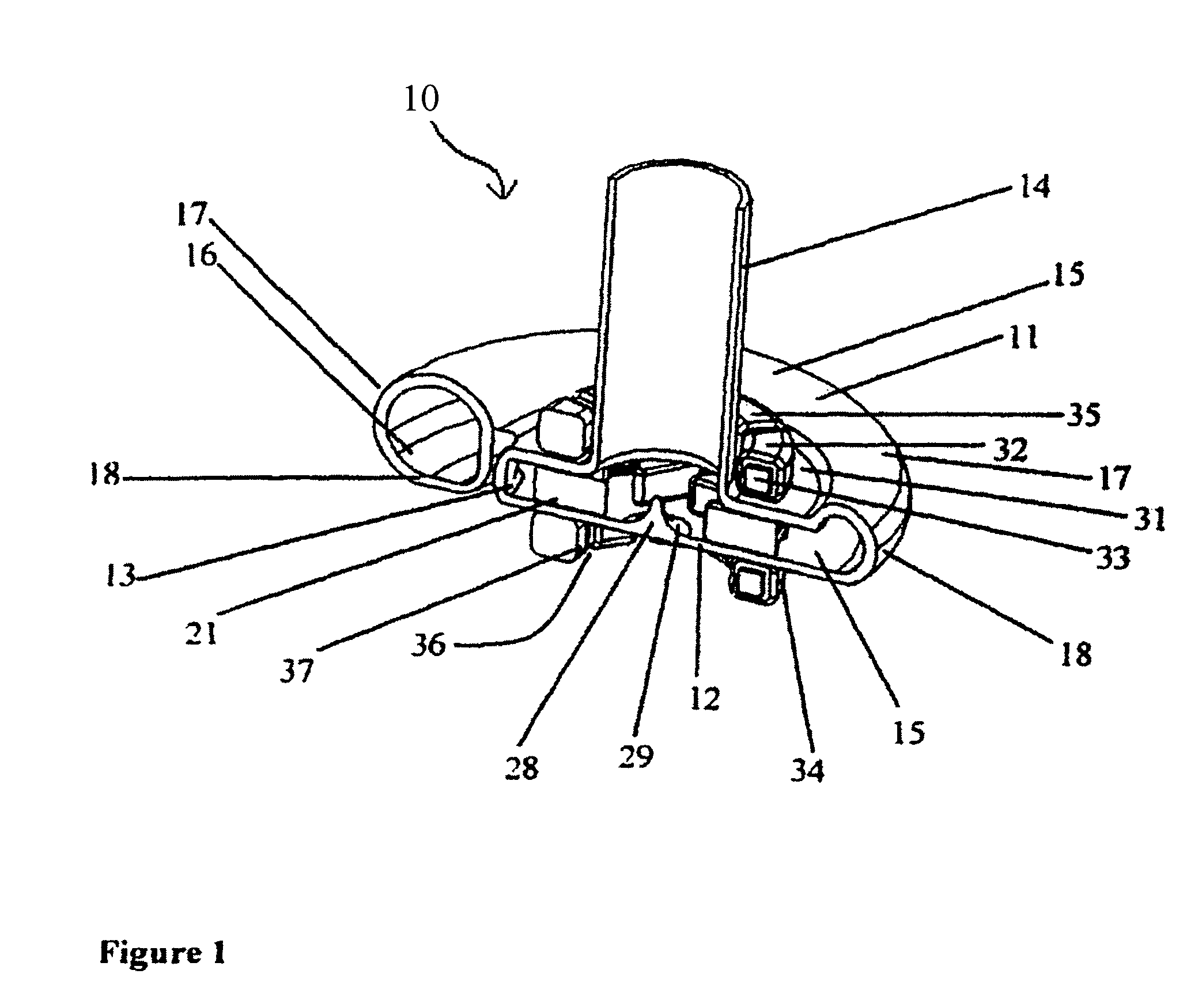
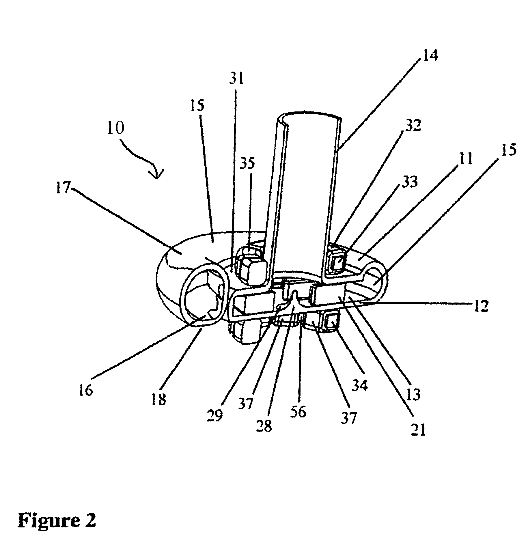
[0052]Embodiments of the present invention provide for small and efficient wearless centrifugal rotary blood pumps having hydrodynamic and magnetic thrust bearings for axial and radial stiffness and improved continuous fluid flow paths within the pump to diminish the risks of hemolysis and thrombosis in the blood being pumped. Other examples of similar blood pumps can be found in U.S. Provisional Patent Application 60 / 758,793 (“the '793 application”), filed Jan. 13, 2006, the disclosure of which is herein incorporated by reference. It is intended that features disclosed herein may be combined with features disclosed in t...


PUM


Abstract

A rotary blood pump may include one or more motor stators overlying exterior surfaces of a wall defining a pumping chamber. A rotatable impeller within the pumping chamber may have a hydrodynamic thrust bearing surface adapted to constrain a position of the impeller along an axis of rotation relative to the wall when the impeller is rotating about the axis of rotation. The impeller position may then be constrained without requiring a constant polarity magnetic force to be applied in the axial direction from a fixed position of the housing.

Description

[0001]This application claims benefit from U.S. Provisional Application No. 60 / 926,855, filed Apr. 30, 2007, the content of which is hereby incorporated herein by reference into this application.CROSS-REFERENCE TO RELATED APPLICATION[0002]The present application claims benefit of the filing date of U.S. Provisional Patent Application No. 60 / 926,885 filed Apr. 30, 2007, the disclosure of which is hereby incorporated by reference herein.FIELD OF THE INVENTION[0003]The present invention relates to rotary pumps and, more specifically, to centrifugal rotary blood pumps and methods of therapeutic support utilizing such pumps, in which a submerged impeller within the pump rotates on wearless hydrodynamic and magnetic bearings to pressure blood to move from a pump inlet to a pump outlet.BACKGROUND OF THE INVENTION[0004]Clinical applications of ventricular assist devices to support patients with end-stage heart disease, as a bridge to cardiac transplantation, or as an end stage therapeutic m...

Claims


Application Information

Patent Timeline
Patent Type & Authority Patents(United States)
IPC IPC(8): F04B17/00A61M1/10F01D3/00
CPCA61M1/101F04D13/0666F04D13/0633F04D13/064F04D29/0473A61M1/1017A61M1/1031A61M1/122Y10S415/90A61M60/824A61M60/422A61M60/148A61M60/546A61M60/857A61M60/232A61M60/523A61M60/592A61M60/165
Inventor LAROSE, JEFFREY A.SHAMBAUGH, JR., CHARLES R.WHITE, DANIEL G.RIVERA, LISANDROTRICHI, KARTIKEYANTHYAGARAJAN, LEGAL REPRESENTATIVE, PALANIVELU
Owner HEARTWARE INC
Learn More