Hydraulic drive system

a drive system and hydraulic technology, applied in the direction of fluid couplings, hoisting equipment, couplings, etc., can solve the problems of increasing packaging space and energy consumption of the system, not being able to achieve satisfactory efficiencies for storage and release of energy, and complex activation, etc., to achieve efficient energy storage and simple activation

Active Publication Date: 2012-04-10
LIEBHERR WERK NENZING
View PDF14 Cites 11 Cited by
  • Summary
  • Abstract
  • Description
  • Claims
  • Application Information

AI Technical Summary

Benefits of technology

[0004]Therefore, it is the object of the present invention to provide a hydraulic drive system which provides for an efficient storage of energy and a simple activation.

Problems solved by technology

With increasing size of the primary drive unit, however, the costs, the packaging space and the energy consumption of the system are also increasing.
In known hydraulic drive systems with such high-pressure accumulator, no satisfactory efficiencies can be achieved for the storage and release of energy.
In addition, activation often is complicated.

Method used


Image

  • Hydraulic drive system
  • Hydraulic drive system
  • Hydraulic drive system

Examples


Embodiment Construction

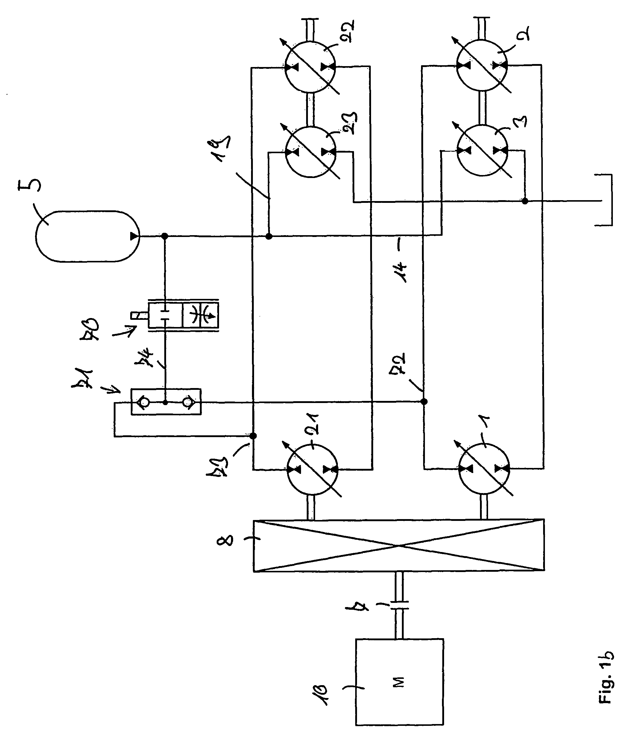
[0079]FIG. 1a now shows an embodiment of the hydraulic drive system of the invention for driving a winch 6. As drive unit 10, a Diesel engine is provided, which drives the first hydraulic displacement machine 1. For this purpose, the drive unit 10 is connected with the first hydraulic displacement machine 1 via a clutch 7 and a transmission 8. The first hydraulic displacement machine 1 is connected with a second hydraulic displacement machine 2 via hydraulic lines 11 and 13, so that a closed primary hydraulic circuit is obtained. The second hydraulic displacement machine 2 is connected with the winch 6 and drives the same.

[0080]Furthermore, a third hydraulic displacement machine 3 is provided, which likewise is connected with the winch 6. Via hydraulic lines, the same is connected with a hydraulic reservoir 9 and a high-pressure accumulator 5. Via a valve 70, the hydraulic accumulator 5 furthermore is connected with the first hydraulic displacement machine 1, namely via the pressure...


PUM


Abstract

The present invention relates to a hydraulic drive system for driving an apparatus, with a drive unit, a first and a second hydraulic displacement machine, with which the drive unit is connectable or connected for transmitting mechanical energy, and a third and a fourth hydraulic displacement machine, which are connectable or connected with the apparatus for transmitting mechanical energy, wherein the first hydraulic displacement machine is hydraulically connected or connectable with the third hydraulic displacement machine, and wherein a high-pressure accumulator is provided, which is hydraulically connected or connectable with the second and the fourth hydraulic displacement machine.

Description

BACKGROUND OF THE INVENTION[0001]The present invention relates to a hydraulic drive system for driving an apparatus, with a drive unit which can drive the apparatus via a primary hydraulic circuit comprising a first and a second hydraulic displacement machine, and with a third hydraulic displacement machine, which is connectable or connected with the apparatus for transmitting mechanical energy, and a high-pressure accumulator which is hydraulically connected or connectable with the third displacement machine. In particular, the present invention relates to a hydraulic drive system which is used in a crane, in particular for driving a winch. Furthermore, the present invention relates to a hydraulic drive system which is used in a mobile equipment, in particular a reachstacker or a wheel loader, in particular as a traveling drive.[0002]Such hydraulic drive systems usually include a primary drive unit, e.g. an internal combustion engine or an electric motor which drives one or more hy...

Claims


Application Information

Patent Timeline
Patent Type & Authority Patents(United States)
IPC IPC(8): F15B1/02B66D1/08
CPCF15B1/024F15B7/006F15B7/008F15B21/14F16H61/4096B66C13/20B66D1/44F15B2211/20546F15B2211/20569F15B2211/212F15B2211/625F15B2211/88
Inventor SCHNEIDER, KLAUSKRAUTLER, WILHELM
Owner LIEBHERR WERK NENZING
Why Eureka
Try Eureka