Z-bar extension member and assembly

a technology of extension member and assembly, which is applied in the field of doors, can solve the problems of increasing the installation time of the door assembly, affecting aesthetics and energy conservation, and inconvenient and time-consuming conventional methods and techniques for trimming z-bars

Active Publication Date: 2012-04-03
LARSON MFG CO OF SOUTH DAKOTA LLC
View PDF36 Cites 7 Cited by
  • Summary
  • Abstract
  • Description
  • Claims
  • Application Information

AI Technical Summary

Benefits of technology

[0015]In certain embodiments, the interior and exterior z-bar members are formed with mating structures such as, but not limited to, projections and apertures or detents and grooves that cooperate to at least temporarily maintain the mated structures in a generally linear positional relationship with respect to each other to assist in the installation and adjustment of the assembly. In other embodiments, structures or cut-away portions may define slots for slidable engagement that imparts a friction between the interior and exterior z-bar members, thereby aiding in holding the adjustment of the length of the assembly.
[0017]An embodiment is also disclosed wherein a guard assembly may be mounted on a vertical edge of the door, the guard assembly having a shield portion that extends at least partially over the z-bar or z-bar assembly. The guard assembly may extend the length of the vertical edge or only a portion thereof to cover at least a corresponding portion of the gap that exists between the vertical edge of the door and the z-bar assembly. The guard assembly may also take the form of an end cap that mounts to and covers an end of the door expander, to retain insulation within the door expander and / or to prevent debris such as dirt and salt from entering the door expander.

Problems solved by technology

Conventional methods and techniques for trimming z-bars are innately inconvenient and time consuming.
A trimming cut that either leaves the z-bar too short or at an improper angle relative to the incline is generally detrimental to the aesthetic and energy conservation qualities of the assembly, and increases the installation time of the door assembly.
While this approach negates the need for cutting the z-bar to length, it does not address the aforementioned detriments to aesthetics and energy conservation.

Method used


Image

  • Z-bar extension member and assembly
  • Z-bar extension member and assembly
  • Z-bar extension member and assembly

Examples


Embodiment Construction

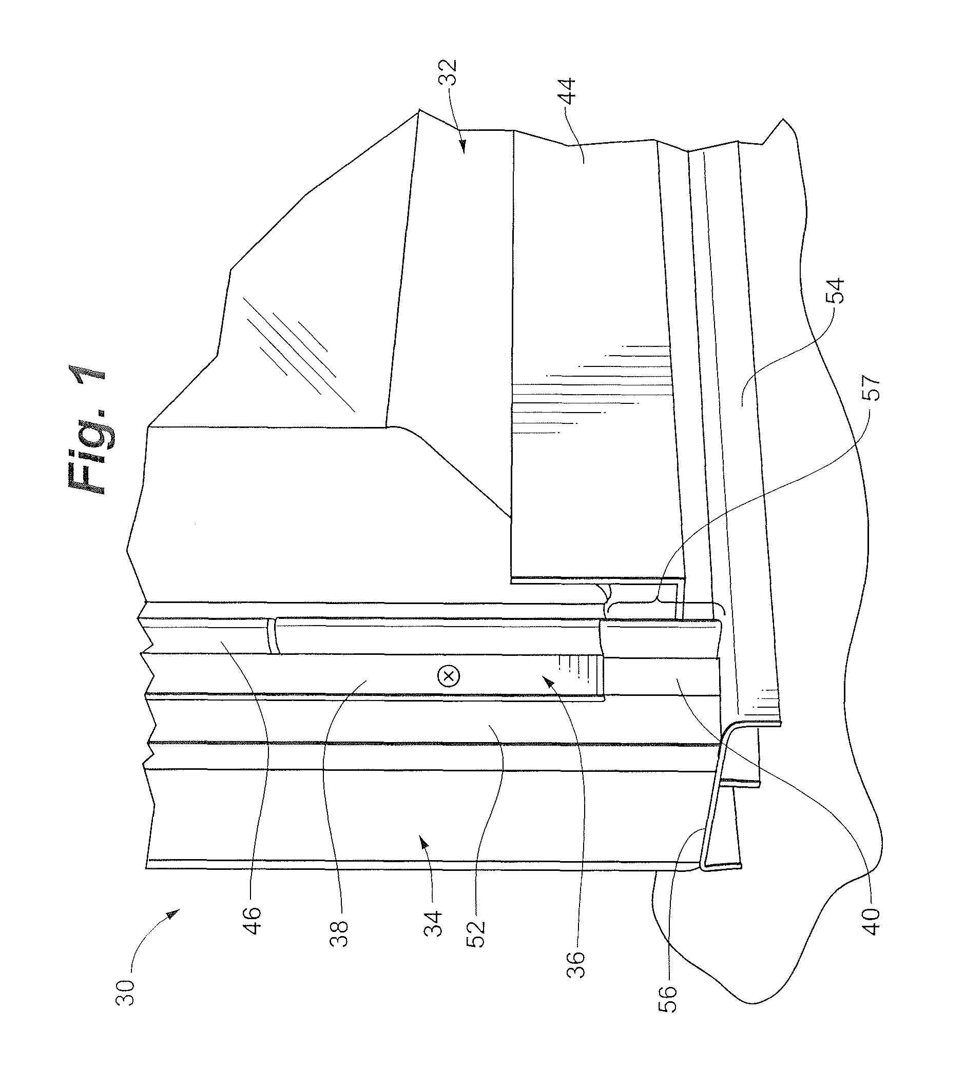
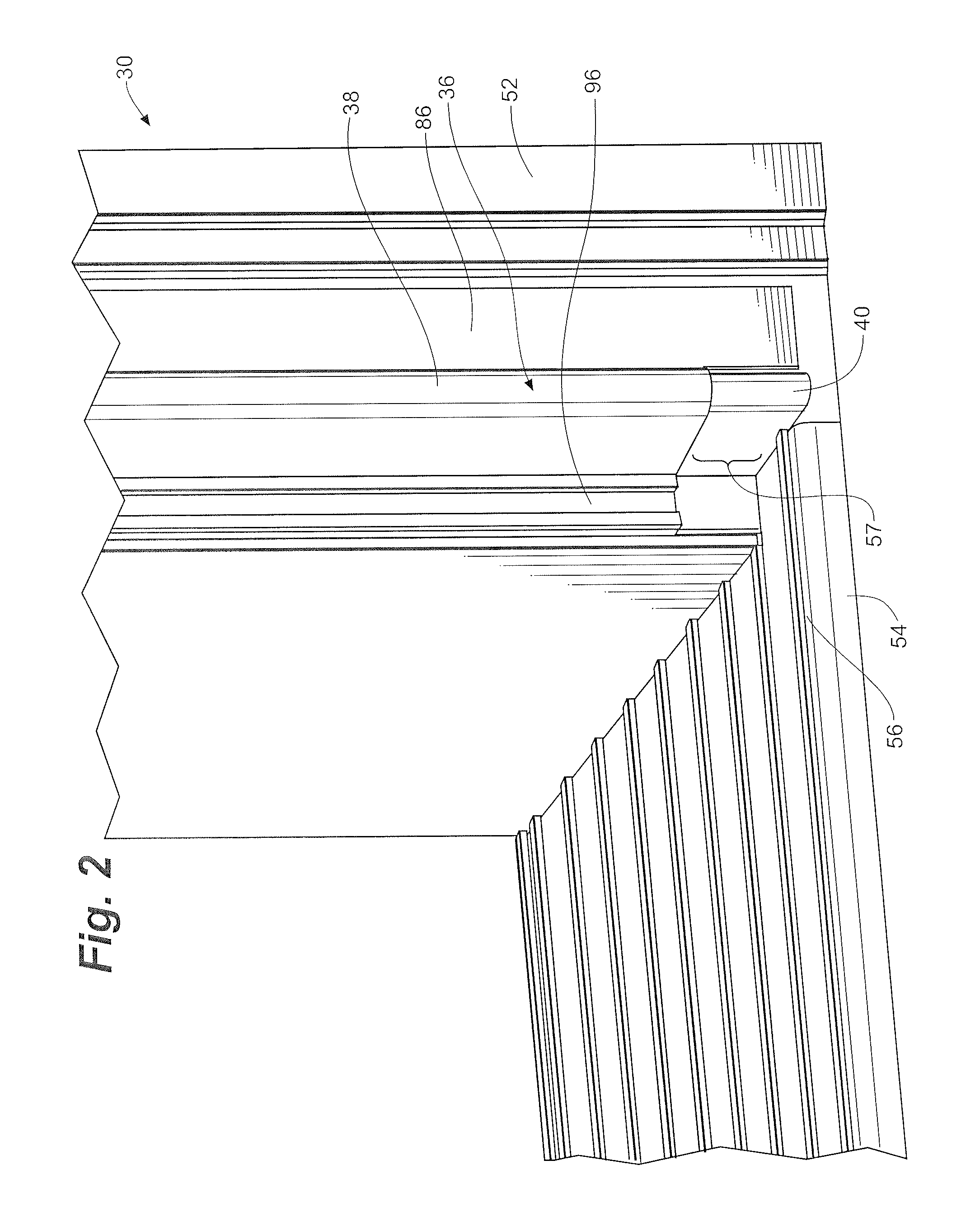
[0048]Referring to FIGS. 1 through 3, a door assembly 30 including an exterior door 32, a door frame or casing 34 and an extended z-bar assembly 36 having a z-bar 38 and a z-bar extension member 40 is depicted in one embodiment of the invention. The exterior door 32, which may be a storm door or a screen door, may include a door expander 44 and a hinge member 46. The door frame or casing 34 may include an exterior trim or door jamb 52, a sill 54 and a header (not depicted). The sill 54 may have an inclined upper surface 56. The z-bar 38 may be dimensioned so that a gap 57 exists between an end of the z-bar 38 and the sill 54. The gap 57 is bridged by the z-bar extension member 40.

[0049]Referring to FIGS. 4 through 8, various embodiments of the extended z-bar assembly are depicted. In one embodiment, the z-bar 38 includes a flange portion 60, a barrel portion 62, a web portion 64 and a projecting portion 66. The z-bar 38 may also be characterized as having an inward-facing surface 67...


PUM


Abstract

An apparatus and method of assembling and using a z-bar extension member for a door installation that negates the need for trimming the assembly. The apparatus includes an exterior z-bar member having an exterior barrel portion and an interior z-bar member having an interior barrel portion. The interior barrel portion is slidably or snappingly engaged within the exterior barrel portion. Mating structures may be included on the cooperating components to maintain a positional relationship therebetween during assembly. A guard assembly that mounts to the edge of a door or on the end of a door expander to cover the gap between the z-bar and the casing is also disclosed that may be used in conjunction with or as an alternative to the z-bar extension member.

Description

RELATED APPLICATION[0001]The present application claims the benefit of U.S. Provisional Application No. 60 / 875,480 filed Dec. 18, 2006, which is incorporated by reference herein in its entirety.FIELD OF THE INVENTION[0002]The present invention relates to doors. More particularly, the present invention relates to z-bar assemblies for doors.BACKGROUND OF THE INVENTION[0003]A door assembly, such as a storm door, often involves the use of what is commonly referred to as a “z-bar.” The z-bars are typically formed to mount the door assembly to the jambs or exterior trim of the entry door. Normally there are two z-bars in such an installation: a hinge-side z-bar and a latch-side z-bar. There may also be a z-bar extending over the top of the door that serves as or facilitates a drip cap. The hinge-side z-bar is so named because it accommodates hinges for pivotal mounting of the door. The latch-side z-bar is so named because it is located adjacent the latch side of the door and may serve as ...

Claims


Application Information

Patent Timeline
Patent Type & Authority Patents(United States)
IPC IPC(8): E06B1/04
CPCE06B1/14E06B2003/7096E06B5/003
Inventor KIBBEL, KEITHNORDGAARD, KELLY
Owner LARSON MFG CO OF SOUTH DAKOTA LLC
Why Eureka
Try Eureka