
Structure for attaching needle guide to ultrasound probe

a needle guide and ultrasound probe technology, applied in the field of medical equipment accessories, can solve the problems of unstable connection between the needle guide and the ultrasound probe, high manufacturing cost and inconvenient operation, and tedious assembly, and achieve the effect of convenient attachment and detachment of the needle guide, stable and firm connection

Active Publication Date: 2012-03-20
SHENZHEN MINDRAY BIO MEDICAL ELECTRONICS CO LTD
View PDF3 Cites 70 Cited by
  • Summary
  • Abstract
  • Description
  • Claims
  • Application Information

AI Technical Summary

Benefits of technology

The solution enables convenient and stable attachment and detachment of the needle guide, reducing operational complexity and manufacturing costs while maintaining a firm connection, facilitating precise ultrasonic inspections and needle punctures.

Problems solved by technology

However, this patent, although addresses the technical problem of detachably assembling a needle guide to an ultrasound probe, suffers from the following disadvantages.
Specifically, on one hand, this patent provides a complex structure which results in tedious assembling, high manufacturing cost and inconvenient operation, and on the other hand, it requires that the material of the mounting seat for the needle guide has high elasticity and plasticity, which leads to an unstable connection between the needle guide and the ultrasound probe.
Other solutions in the prior art for attaching a needle guide to an ultrasound probe also have the shortages of complex structure, unstable connection, inconvenient operation, etc.

Method used


Image

  • Structure for attaching needle guide to ultrasound probe
  • Structure for attaching needle guide to ultrasound probe
  • Structure for attaching needle guide to ultrasound probe

Examples


Embodiment Construction

[0033]An embodiment of the structure for attaching a needle guide to an ultrasound probe according to the present invention will now be described with reference to the figures, wherein like numbers represent like parts.

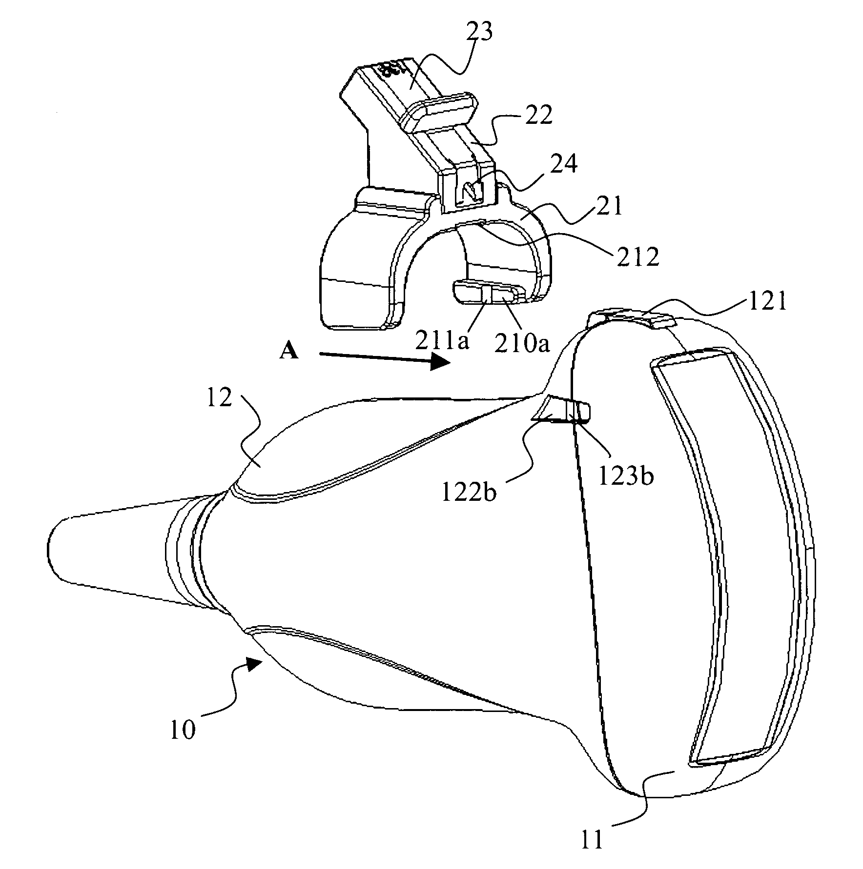
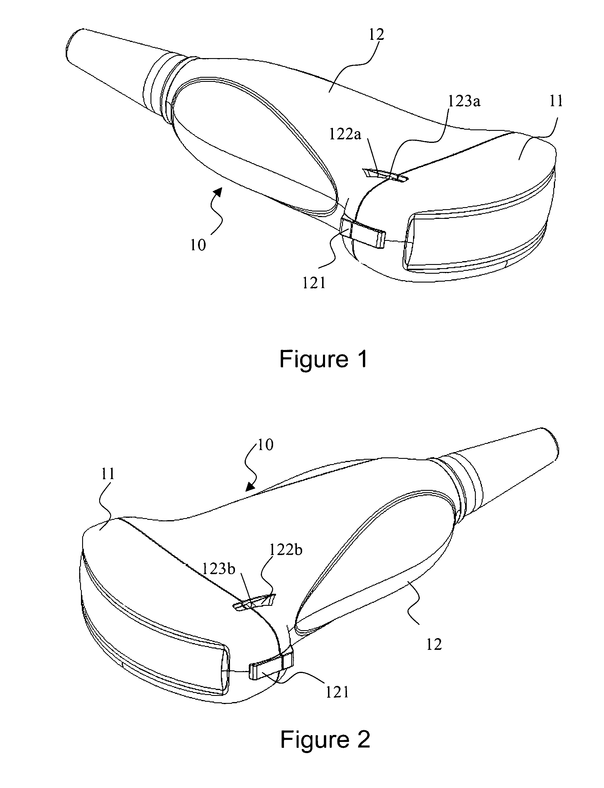
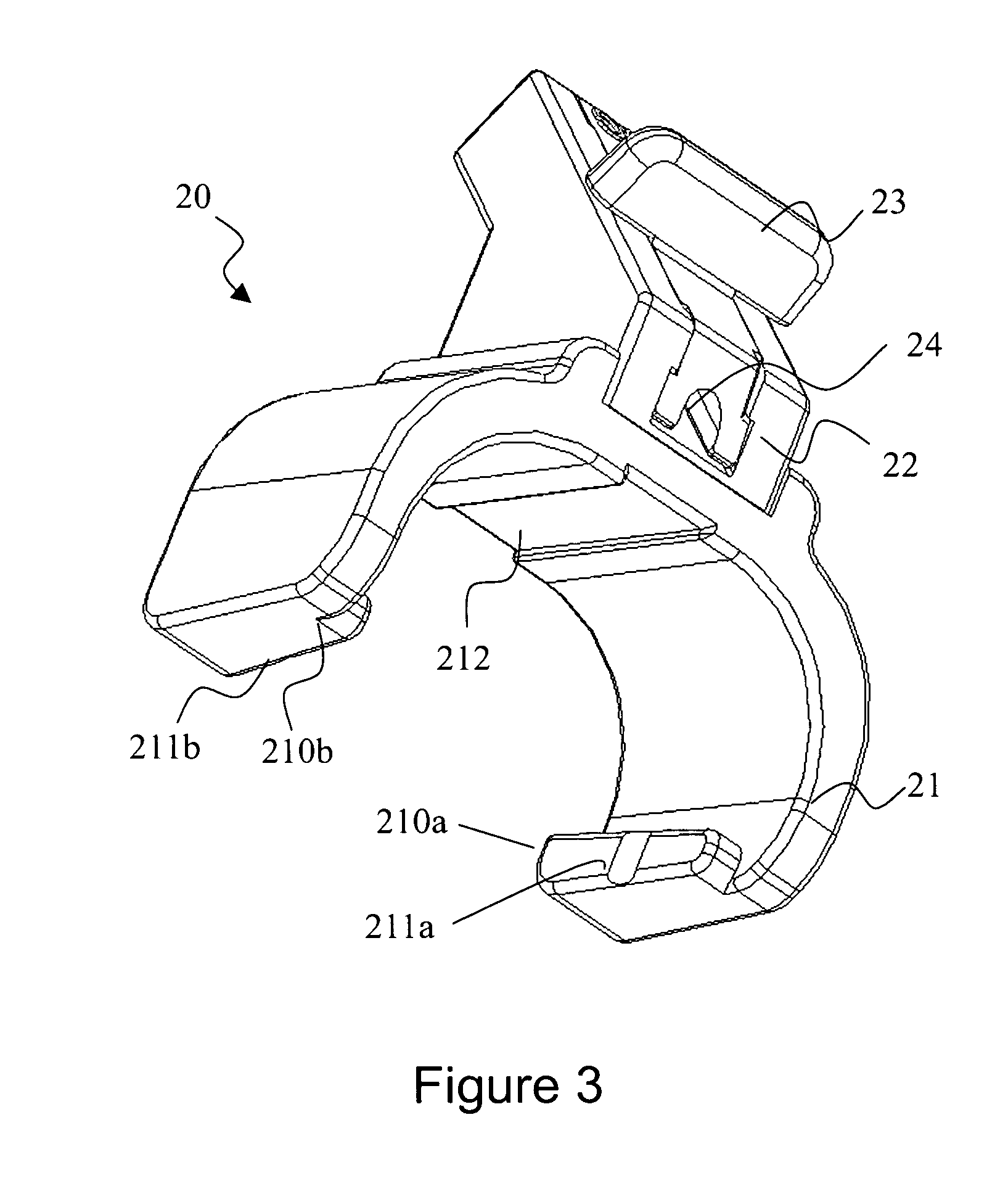
[0034]As shown in FIG. 6, a structure for attaching a needle guide to an ultrasound probe according to the present invention comprises a probe casing 10 and a needle guide 20. The probe casing 10 comprises a head part 11 provided at a front side of the probe casing and a grasping part 12 provided at a back side of the probe casing and connected with the head part 11. Herein the term “front side” refers to the side proximal to the person inspected by the ultrasonic diagnosis apparatus (or the patient), while the term “back side” refers to the side distal to the person inspected by the ultrasonic diagnosis apparatus (or the patient). The needle guide 20 comprises a generally “C”-shaped or arcuate clip 21 for clamping onto the probe casing. As shown in FIGS. 1 and 2, the...


PUM


Abstract

A structure for attaching a needle guide to an ultrasound probe is provided, which includes a probe casing and a needle guide. The probe casing includes a head part provided at a front side of the probe casing and a grasping part provided at a back side of the probe casing and connected with the head part. The needle guide includes a generally “C”-shaped or arcuate clip adapted to be clamped onto the probe casing. The probe casing has opposite outer surfaces each being formed with an outwardly opened and elongated guiding slot extended along a front-back direction. The clip has two clamping arms, each clamping arm having an inner surface opposing to that of the other clamping arm, each inner surface being provided with an elongated clamping protrusion adapted to match and fit with the guiding slot of the probe casing. The clamping protrusions provided on the clamping arm extend in a direction generally perpendicular to the protruding direction of the clamping arms. The structure for attaching a needle guide to an ultrasound probe of the present disclosure is advantageous over the existing structures of the prior art in that the structure is simple, the connection is firm, and the operation is convenient.

Description

FIELD OF THE INVENTION[0001]The present invention relates to an accessory for medical equipment, and especially to an attachment structure for attaching a needle guide to an ultrasound probe.BACKGROUND ART[0002]Ultrasound probes used in ultrasonic diagnosis apparatus comprise a type of typical ultrasound probes and another type of ultrasound probes equipped with a needle guide for holding a needle such as a puncture needle. In order to conveniently manipulate an ultrasound probe and in the mean while perform needle-puncturing operation in a precise way, people have made corresponding improvements to ultrasound probes and needle guides so that they can be assembled together and detached from each other. For example, U.S. Pat. No. 5,623,931 discloses a technical solution and a concrete structure for assembling and detaching a needle guide with respect to an ultrasound probe. However, this patent, although addresses the technical problem of detachably assembling a needle guide to an ul...

Claims


Application Information

Patent Timeline
Patent Type & Authority Patents(United States)
IPC IPC(8): A61B17/34
CPCA61B8/0833A61B8/0841A61B8/4455A61B17/3403A61B2017/3413A61M5/3287
Inventor HUANG, SHANZHIZHANG, MENGYUEZOU, JIANFENG
Owner SHENZHEN MINDRAY BIO MEDICAL ELECTRONICS CO LTD
Learn More