
Retractor with flexible sleeve

a flexible sleeve and retraction technology, which is applied in the direction of trocar, cannula, surgery, etc., can solve the problems of inability to adjust the length of the cannula, the thickness of the abdominal tissue which must be traversed by the cannula, and the inability to retraction the cannula, so as to improve the retention and stability of the device in the tissue, the effect of optimizing the device length and improving the tissue retraction ra

Active Publication Date: 2012-03-20
CILAG GMBH INT
View PDF279 Cites 49 Cited by
  • Summary
  • Abstract
  • Description
  • Claims
  • Application Information

AI Technical Summary

Benefits of technology

The device optimizes cannula length, enhances tissue retraction and retention, and maintains a fluid-tight seal even during angulation, reducing the need for external stability devices and accommodating a range of tissue thicknesses.

Problems solved by technology

One problem with existing methods and devices is that the thickness of abdominal tissue which must be traversed by the cannula varies from patient to patient.
This process is cumbersome and can result in the insertion of cannulas that have an excess length within the patient.
When cannulas are placed in close proximity to each other, such excess cannula length can cause interference between working channels and the instruments passed therethrough.
The excess length can potentially cause damage to patient tissue if the excess length is significant.
Another drawback to existing access devices is that they do not retract tissue beyond the initial incision to any appreciable degree.
Instead, they generally have a rigid body with a straight tubular shape that dramatically limits the range of angles at which surgical instruments can be positioned when passed therethrough.
Angulation of such instruments thus requires angulation of the entire access device, which can cause these existing devices to suffer from decreased retention and stability and from poor seal integrity between the access device and adjacent tissue.

Method used


Image

  • Retractor with flexible sleeve
  • Retractor with flexible sleeve
  • Retractor with flexible sleeve

Examples


Embodiment Construction

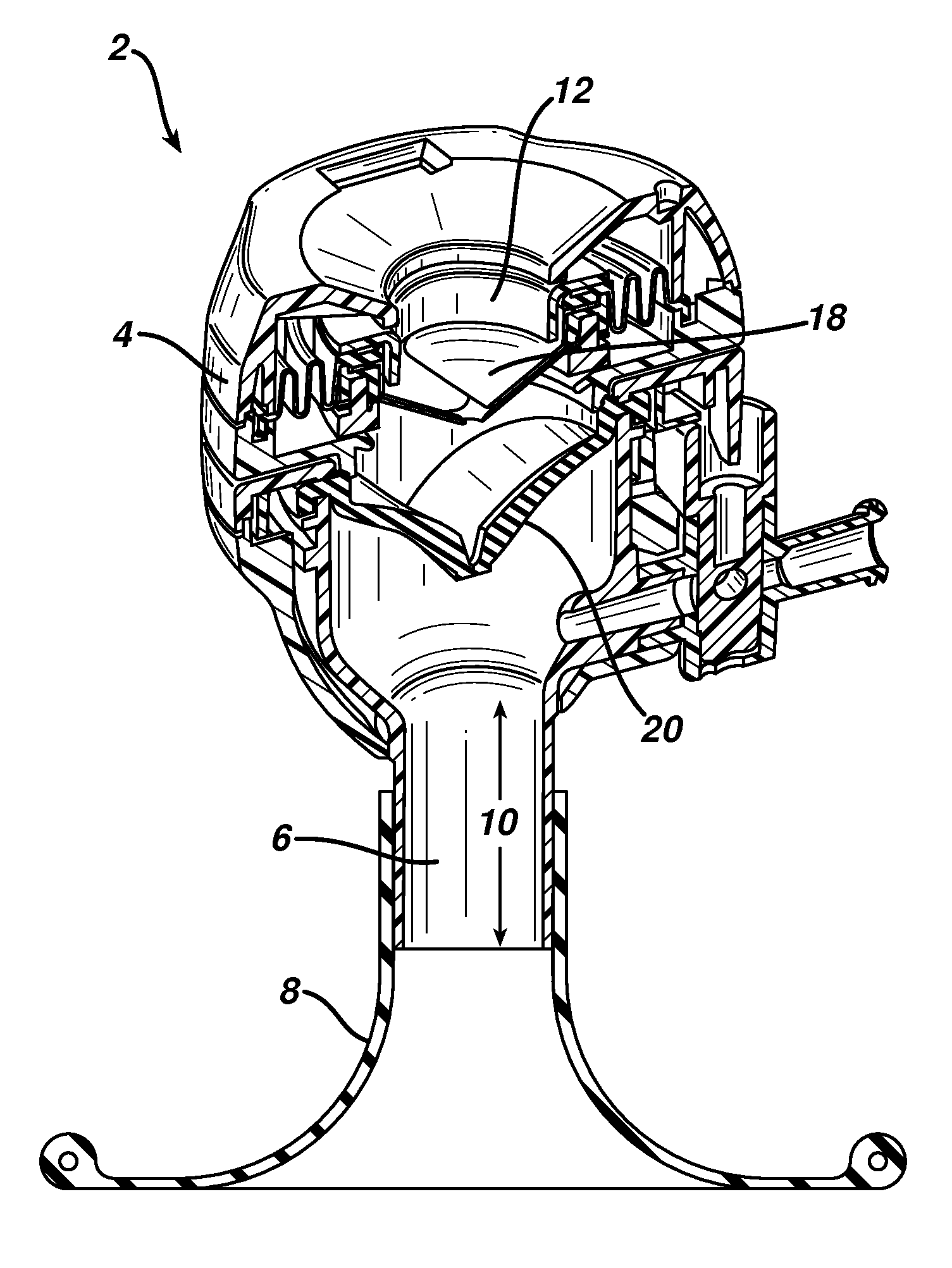
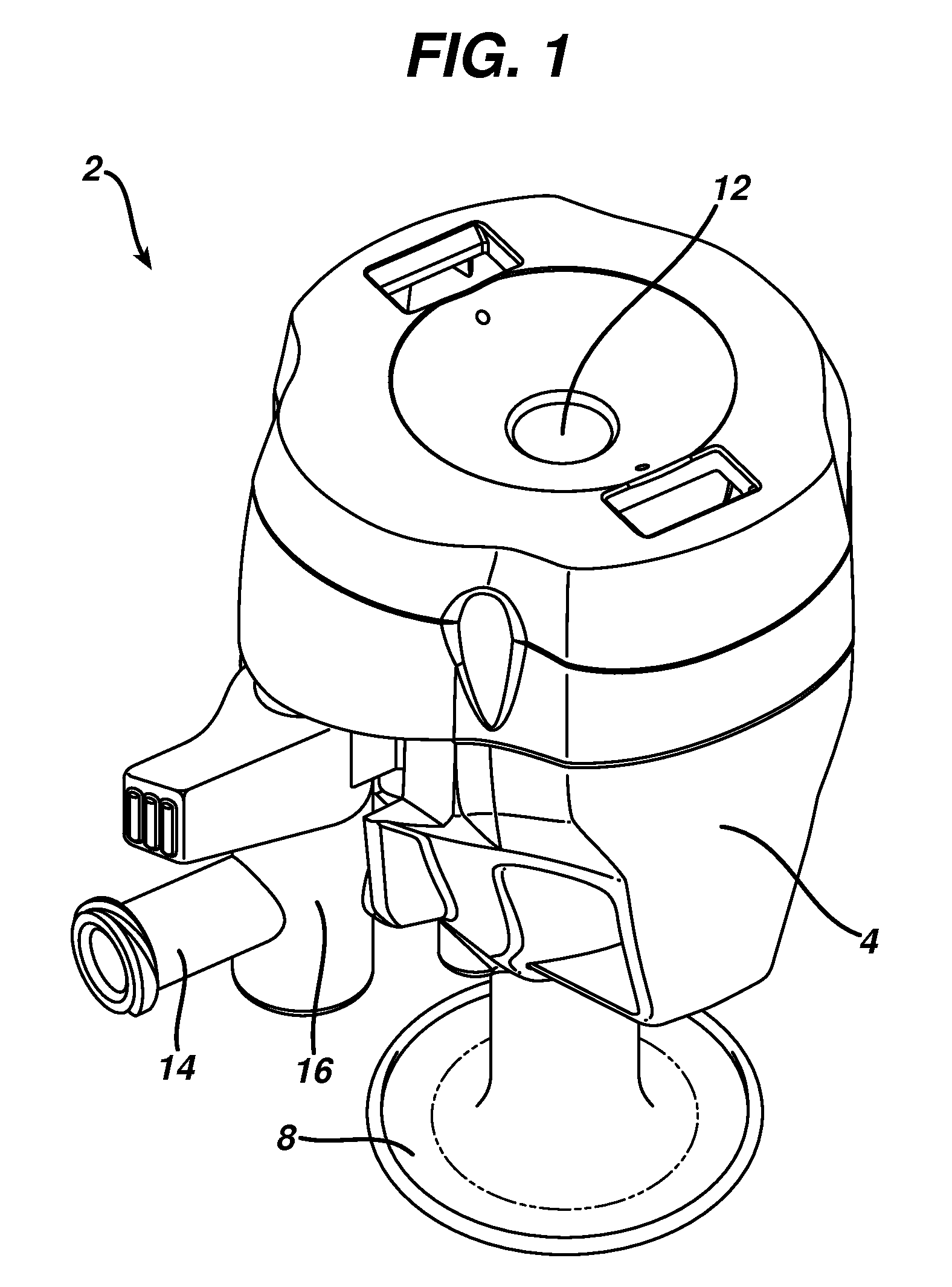
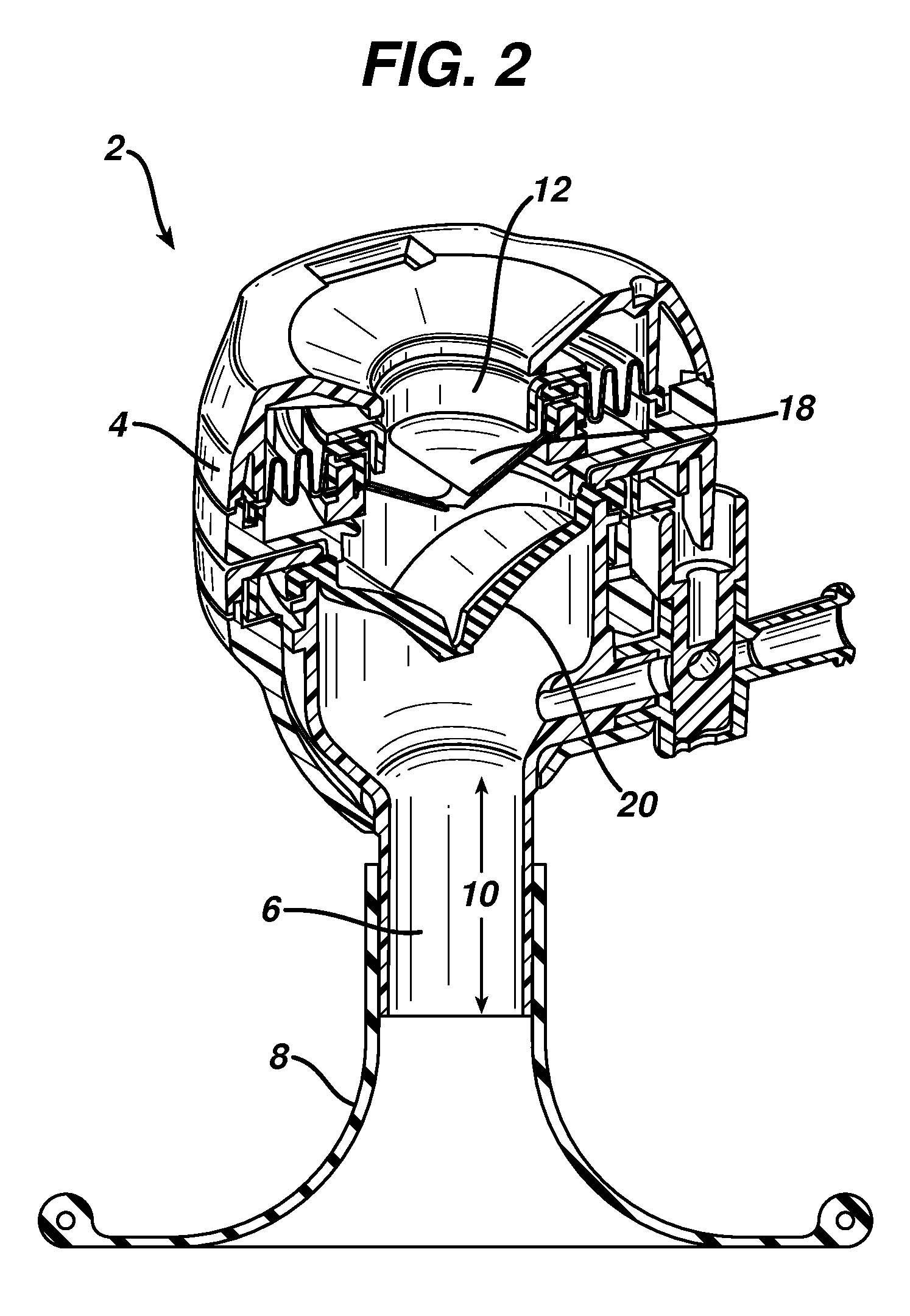
[0046]Certain exemplary embodiments will now be described to provide an overall understanding of the principles of the structure, function, manufacture, and use of the devices and methods disclosed herein. One or more examples of these embodiments are illustrated in the accompanying drawings. Those skilled in the art will understand that the devices and methods specifically described herein and illustrated in the accompanying drawings are non-limiting exemplary embodiments and that the scope of the present invention is defined solely by the claims. The features illustrated or described in connection with one exemplary embodiment may be combined with the features of other embodiments. Such modifications and variations are intended to be included within the scope of the present invention.

[0047]A person skilled in the art will appreciate that, while methods and devices are described herein in connection with minimally invasive laparoscopic procedures in the abdominal cavity, the method...


PUM


Abstract

Devices and methods are disclosed for accessing a body cavity or other surgical site while providing optimal device length and improved tissue retraction, device retention and stability, and seal integrity. A surgical access device is disclosed that generally comprises an external seal housing having at least one working channel and that is coupled to a flexible and / or resilient retractor. The retractor can include a resilient ring at its distal circumference configured to be deformed to facilitate insertion through an incision and then to return to an undeformed state having a diameter greater than a diameter of the incision once within a body cavity. Various means of coupling the retractor to the housing are disclosed, as are various types of seals that can be included within the housing. “Low-profile”and “peel-away cannula” embodiments of the surgical access device are disclosed, along with methods of accessing a body cavity using such devices.

Description

FIELD OF THE INVENTION[0001]The present invention relates to methods and devices for performing surgical procedures, and in particular to methods and devices for accessing a body cavity.BACKGROUND OF THE INVENTION[0002]In many surgical procedures, it is desirable to provide one or more working channels into a body cavity through which various instruments can be passed to view, engage, and / or treat tissue to achieve a diagnostic or therapeutic effect. In laparoscopic abdominal procedures for example, the abdominal cavity is generally insufflated with CO2 gas to a pressure of around 15 mm Hg. The abdominal wall is pierced and one or more tubular cannulas, each defining a working channel, are inserted into the abdominal cavity. A laparoscopic telescope connected to an operating room monitor can be used to visualize the operative field and can be placed through one of the working channels. Other laparoscopic instruments such as graspers, dissectors, scissors, retractors, etc. can also b...

Claims


Application Information

Patent Timeline
Patent Type & Authority Patents(United States)
IPC IPC(8): A61B1/32
CPCA61B17/3423A61B17/3462A61B2017/3447A61B2017/3464A61B2017/3466A61B2017/349
Inventor SHELTON, IV, FREDERICK E.WIDENHOUSE, CHRISTOPHER W.
Owner CILAG GMBH INT
Learn More