Driving device and driving method of electric discharge lamp, light source device, and image display apparatus

a technology of driving device and electric discharge lamp, which is applied in the direction of electrical equipment, instruments, light sources, etc., can solve the problems of increasing voltage applied at the time of predetermined power supply, limited use period of high intensity discharge lamp, and increasing length of ar

Active Publication Date: 2012-03-06
SEIKO EPSON CORP
View PDF10 Cites 1 Cited by
  • Summary
  • Abstract
  • Description
  • Claims
  • Application Information

AI Technical Summary

Benefits of technology

[0007]It is an advantage of some aspects of the invention to provide a technology for increasing use period of an electric discharge lamp.

Problems solved by technology

When the high intensity discharge lamp is lighted with AC ramp current having modulated pulse width, the period for use of the high intensity discharge lamp is limited due to deterioration of electrodes or deposition (blacking) of electrode material on the interior of the high intensity discharge lamp.
This problem arises not only from the high intensity discharge lamp but also from various types of discharge lamp (electric discharge lamp) which emit light by arc discharge between electrodes.
Generally, the length of arc increases as an electrode deteriorates, and thus voltage applied at the time of predetermined power supply rises.

Method used


Image

  • Driving device and driving method of electric discharge lamp, light source device, and image display apparatus
  • Driving device and driving method of electric discharge lamp, light source device, and image display apparatus
  • Driving device and driving method of electric discharge lamp, light source device, and image display apparatus

Examples


first embodiment

A. First Embodiment

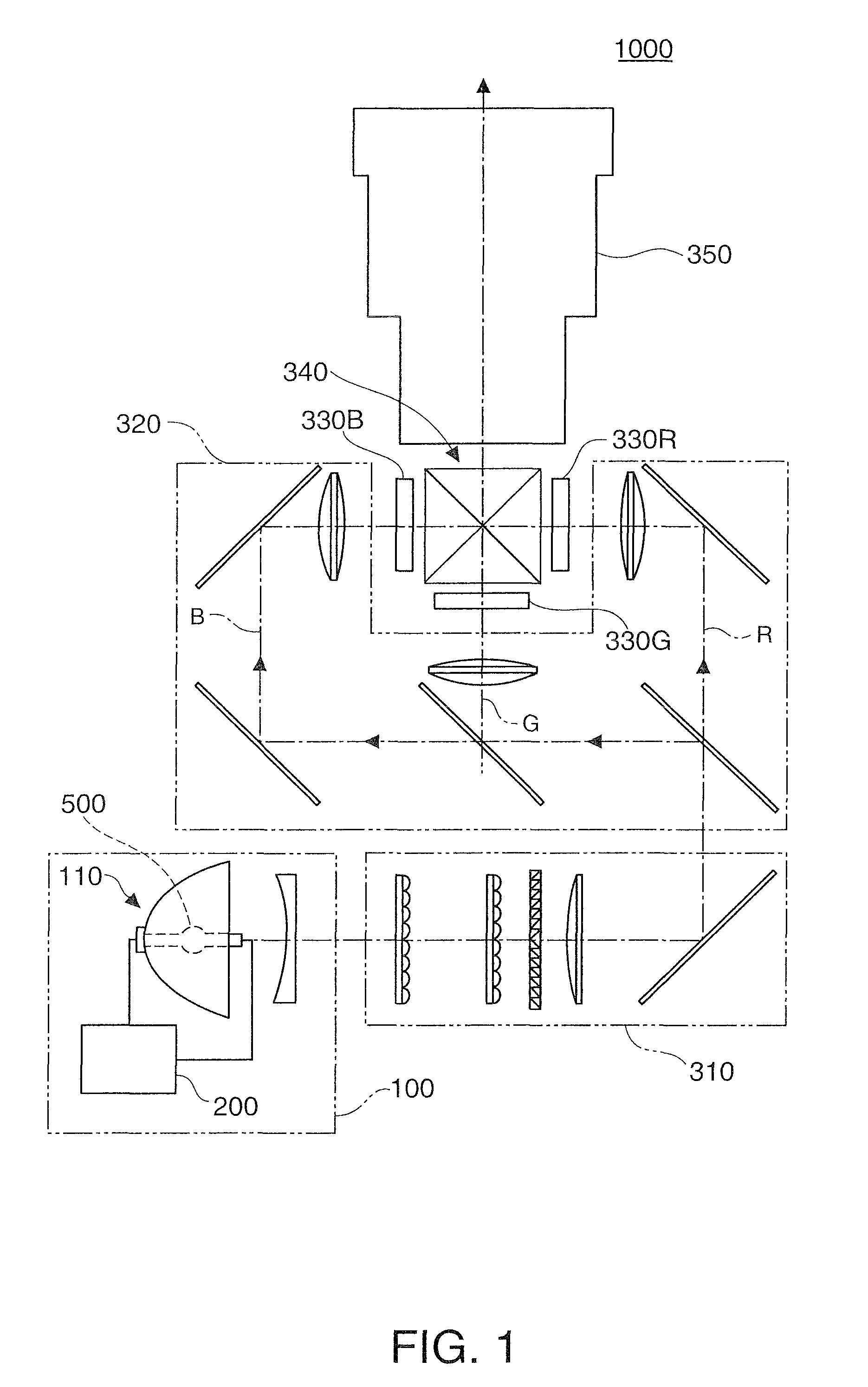
[0042]FIG. 1 schematically illustrates a structure of a projector 1000 according to a first embodiment of the invention. The projector 1000 includes a light source device 100, an illumination system 310, a color separation system 320, three liquid crystal light valves 330R, 330G, and 330B, a cross dichroic prism 340, and a projection system 350.

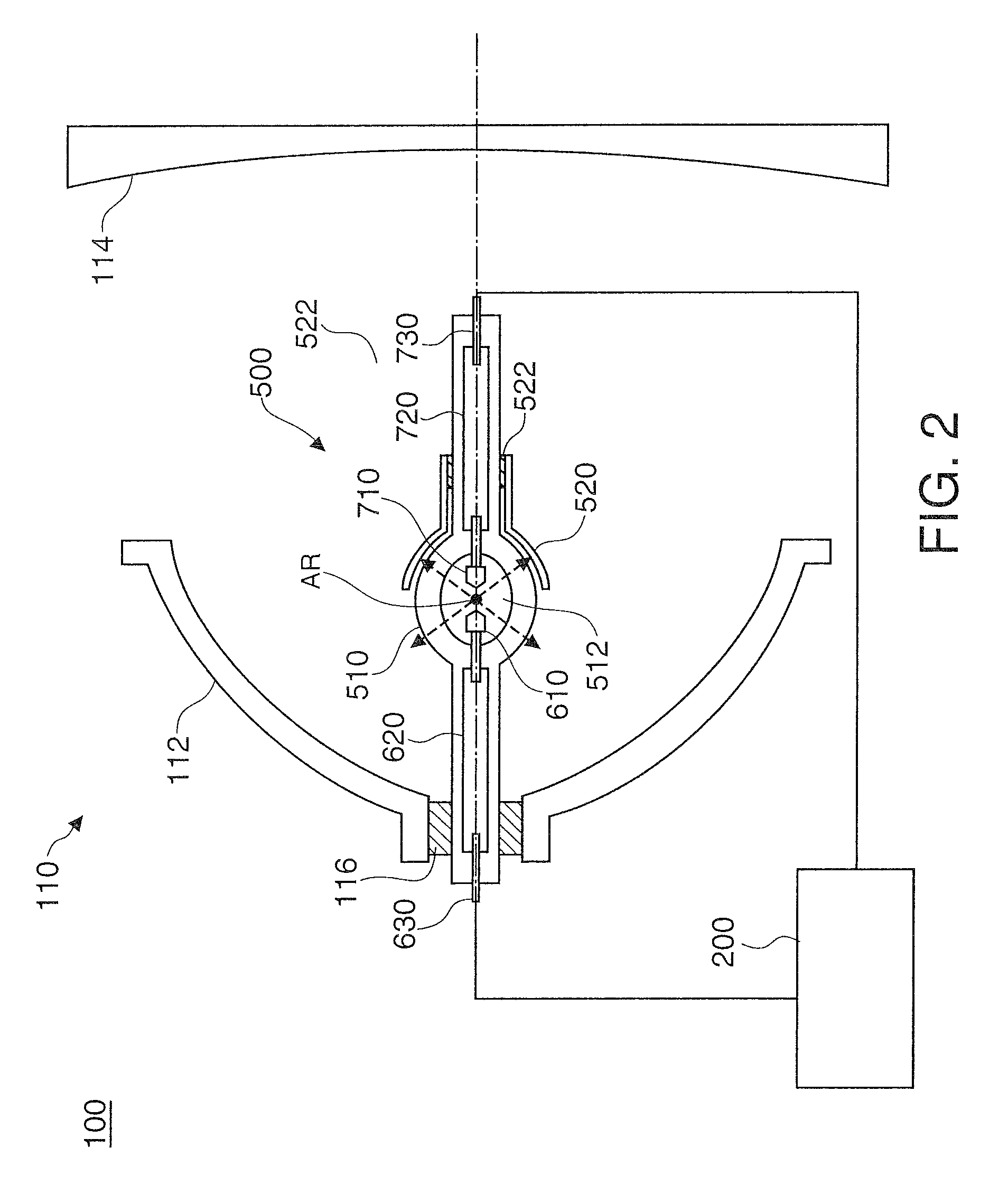
[0043]The light source device 100 has a light source unit 110 including an electric discharge lamp 500, and a discharge lamp driving device 200 for driving the electric discharge lamp 500. The electric discharge lamp 500 discharges by receiving supply of electric power from the discharge lamp driving device 200. The light source unit 110 supplies lights emitted from the electric discharge lamp 500 toward the illumination system 310. The specific structures and functions of the light source unit 110 and the discharge lamp driving device 200 will be described later.

[0044]The illuminances of the lights emitted from the light s...

second embodiment

B. Second Embodiment

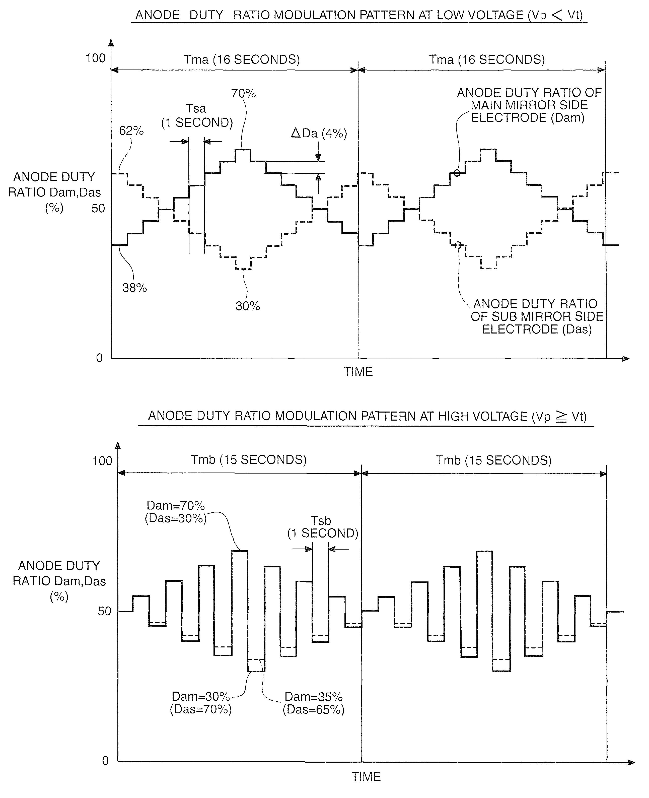
[0074]FIG. 12 shows a modulation pattern used when the ramp voltage Vp is equal to or higher than the threshold voltage Vt in a second embodiment. According to the modulation pattern at high voltage in the second embodiment, a period in which the anode duty ratio Dam is lower than the reference duty ratio (50%) (low duty ratio period) is reduced in the first half of the modulation cycle Tmc, and a period in which the anode duty ratio Dam is higher than the reference duty ratio (high duty period) is reduced in the second half of the modulation cycle Tmc. Other points are similar to those in the first embodiment.

[0075]While the anode duty ratio of one electrode is high, the temperature of the corresponding electrode increases. When the electrode operates as cathode at the increased temperature, release of electrode material into the discharge space 512 (sputter) caused by collision of cations (such as Ar+ and Hg+) generated by discharge increases. As a result, blac...

third embodiment

C. Third Embodiment

[0079]FIGS. 13A and 13B show the operation of the electric discharge lamp 500 according to a third embodiment. FIG. 13A shows a modulation pattern of duty ratios at low voltage. FIG. 13A is the same as FIG. 7A, and the explanation is not repeated herein. Solid lines in FIG. 13B show changes of the ramp current Ip with time for each of the three periods T1 through T3 in the third embodiment, and broken lines show changes of the ramp current Ip with time for each of the three periods T1 through T3 in the first embodiment. The ramp current Ip at high voltage is set based on the established anode duty ratio in the same manner as at low voltage shown in FIG. 13B.

[0080]As shown in FIG. 13B, triangular waves are superimposed on the ramp current Ip in the period in which the duty ratio exceeds the reference duty ratio (50%) in the third embodiment. In this case, the absolute value (level) of the ramp current Ip at the last end of the corresponding period is set at a value...


PUM


Abstract

A driving device of an electric discharge lamp includes: a discharge lamp lighting unit which supplies power to the electric discharge lamp while alternately switching polarity of voltage applied between two electrodes of the electric discharge lamp to lighting the electric discharge lamp; and an anode duty ratio modulating unit which sets at least a first retention period and a second retention period having an anode duty ratio different from that of the first retention period and provided after the first retention period to modulate the anode duty ratios, assuming that each of the retention periods is a period for retaining an anode duty ratio as ratio of an anode period in which one of the electrodes operates as anode at a constant value in one cycle of the polarity switching, wherein the anode duty ratio modulating unit has a first modulation mode for operating the electric discharge lamp in steady condition and a second modulation mode for providing larger change of the anode duty ratio between the first retention period and the second retention period than change of the first modulation mode.

Description

[0001]This application claims priority to Japanese Application No. 2008-204637 filed in Japan on Aug. 7, 2008, the disclosure of which is hereby incorporated by reference in its entirety.BACKGROUND[0002]1. Technical Field[0003]The present invention relates to a technology for driving an electric discharge lamp which emits light by discharge generated between electrodes.[0004]2. Related Art[0005]A high intensity discharge lamp such as high-pressure gas discharge lamp is used as a light source of an image display apparatus such as projector. For lighting the high intensity discharge lamp, alternating current (AC ramp current) is supplied to the high intensity discharge lamp. As a method for lighting the high intensity discharge lamp by the supply of AC ramp current, such a technology has been proposed which uses AC ramp current having an approximately constant absolute value and modulated pulse width ratio of positive and negative pulse widths to be supplied to the high intensity disc...

Claims


Application Information

Patent Timeline
Patent Type & Authority Patents(United States)
IPC IPC(8): H05B41/36
CPCH05B41/2928
Inventor YAMAUCHI, KENTAROTERASHIMA, TETSUO
Owner SEIKO EPSON CORP
Why Eureka
Try Eureka