
Electrophoretic medium with gaseous suspending fluid

Inactive Publication Date: 2012-03-06
E INK CORPORATION
View PDF166 Cites 66 Cited by
  • Summary
  • Abstract
  • Description
  • Claims
  • Application Information

AI Technical Summary

Benefits of technology

[0018]This invention also provides a second process for producing an electrophoretic medium of the invention. This second process comprises admixing particles with a material capable of generating gas; dispersing the mixture of particles and gas-generating material in a curable binder; at least partially curing the binder; and exposing the gas-generating material to conditions effective to cause generation of gas therefrom, thereby causing the formation within the binder of capsules containing the particles. In this process, the gas-generating material may comprise a volatile liquid and the gas be formed by evaporation of the liquid. Alternatively, the gas may be generated by reaction of the gas-generating material with a material present in the binder.
[0019]This invention also provides a third process for producing an electrophoretic medium of the invention. This third process comprises admixing a material capable of generating gas with a wall-forming material; exposing the gas-generating material to conditions effective to cause generation of gas therefrom, thereby causing the formation of gas-filled cavities within the wall-forming material; and introducing solid particles into the cavities.
[0020]Finally, this invention provides a fourth process f

Problems solved by technology

Nevertheless, problems with the long-term image quality of these displays have prevented their widespread usage.
For example, particles that make up electrophoretic displays tend to settle, resulting in inadequate service-life for these displays.
Unencapsulated electrophoretic media using gaseous suspending fluids are known (see, for example, Kitamura, T., et al., “Electrical toner movement for electronic paper-like display”, IDW Japan, 2001, Paper HCS1-1, and Yamaguchi, Y., et al., “Toner display using insulative particles charged triboelectrically”, IDW Japan, 2001, Paper AMD4-4) and such gas-based electrophoretic media appear to be susceptible to the same types of problems due to particle settling as liquid-based electrophoretic media, when the media are used in an orientation which permits such settling, for example in a sign where the medium is disposed in a vertical plane.
Indeed, particle settling appears to be a more serious problem in gas-based electrophoretic media than in liquid-based ones, since the lower viscosity of gaseous suspending fluids as compared with liquid ones allows more rapid settling of the electrophoretic particles.

Method used


Image

  • Electrophoretic medium with gaseous suspending fluid
  • Electrophoretic medium with gaseous suspending fluid
  • Electrophoretic medium with gaseous suspending fluid

Examples


Embodiment Construction

[0024]The aforementioned Kitamura paper describes an electrophoretic imaging system based on particles moving in air under the influence of a field. A transition between black and white optical states is achieved with a switching time of about one millisecond. The electrophoretic particles comprise a black, conductive polymeric bead, which can be reversibly charged by contact with a charge transfer layer (a mixture of a polycarbonate and (N,N-diethylamino)benzaldehyde diphenyl hydrazone, coated in a 1:1 weight ratio) on indium tin oxide (ITO) coated glass. Depending on the polarity of the applied voltage, the charged particles are either visible (black state) or hidden behind a non-charging cloud of white particles (white state) composed of a material denoted “carbon fluoride”. The operating voltage is greater than 100 V, and the optical contrast ratio is only about 2. However, the aforementioned Yamaguchi paper, which describes a system in which the electrophoretic particles are tr...


PUM

PropertyMeasurementUnit
Areaaaaaaaaaaa
Electrophoreticaaaaaaaaaa
Electric fieldaaaaaaaaaa

Abstract

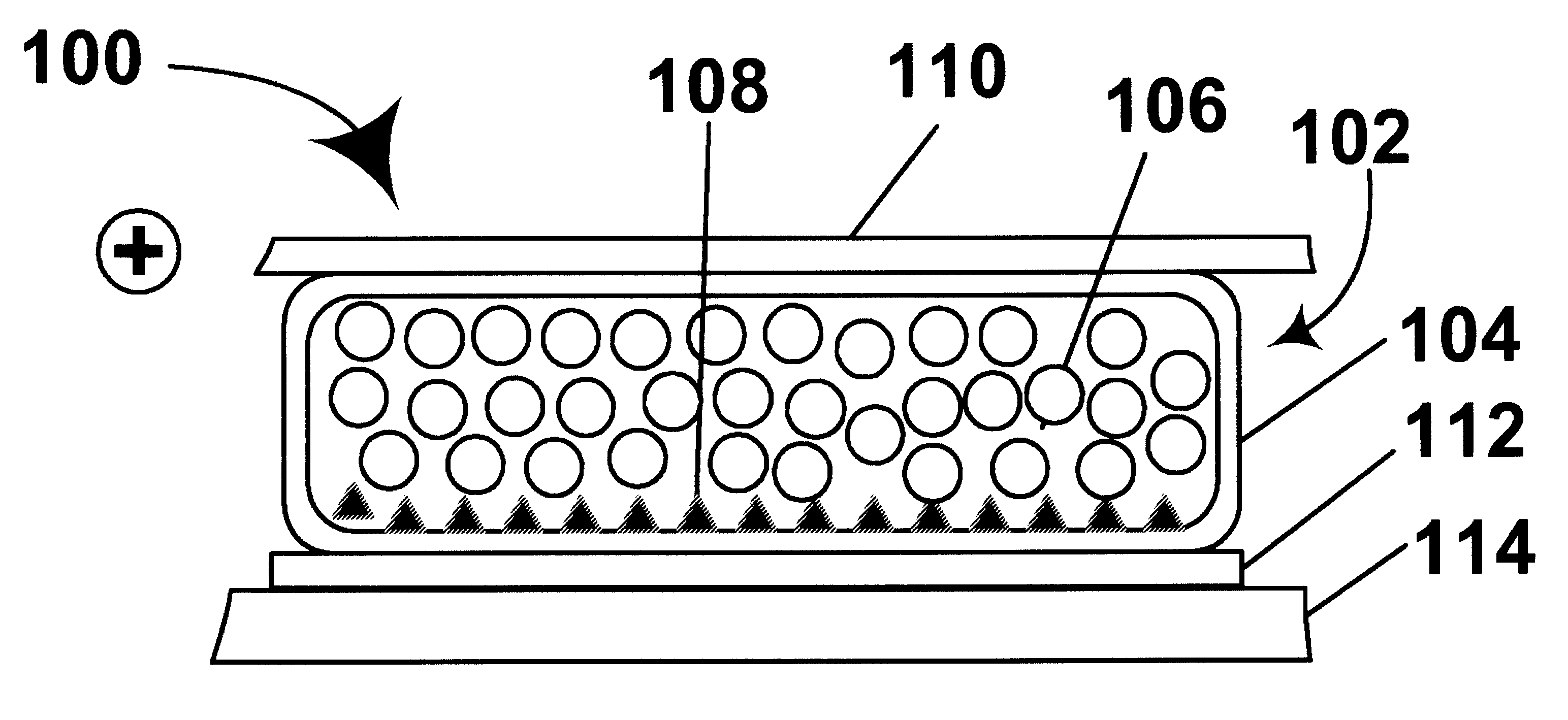
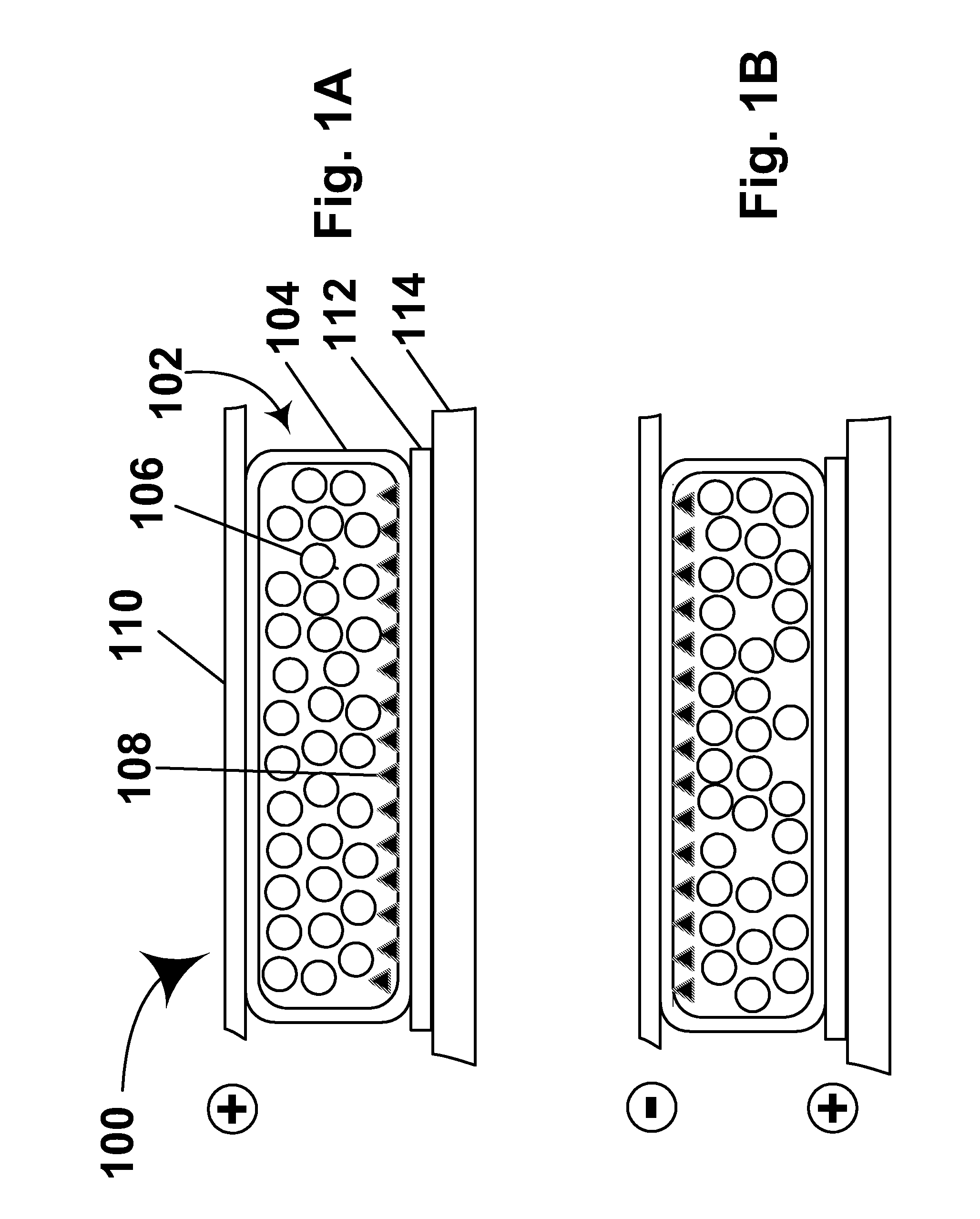
An electrophoretic medium (102) comprises a plurality of capsules (104), each capsule comprising an internal phase comprising a plurality of electrophoretically mobile particles (106, 108) in a gaseous suspending medium, and a capsule wall surrounding the internal phase. Various processes for producing such an electrophoretic medium are also described.

Description

CROSS REFERENCE TO RELATED APPLICATIONS[0001]This invention claims priority from Provisional Application Ser. No. 60 / 319,517, filed Sep. 3, 2002. The entire disclosure of this application, and of all other patents and applications referred to below, is herein incorporated by reference.BACKGROUND OF INVENTION[0002]This invention relates to an electrophoretic medium with a gaseous suspending fluid. More specifically, this invention relates to an encapsulated electrophoretic medium with a gaseous suspending fluid.[0003]Electrophoretic displays have been the subject of intense research and development for a number of years. Such displays can have attributes of good brightness and contrast, wide viewing angles, state bistability, and low power consumption when compared with liquid crystal displays. (The terms “bistable” and “bistability” are used herein in their conventional meaning in the art to refer to displays comprising display elements having first and second display states differi...

Claims


Application Information

Patent Timeline
IPC IPC(8): B23K10/00G02F1/16757G09F9/37
CPCG02F1/167G09F9/372G02F2001/1674G02F1/1671G02F1/16757
Inventor JACOBSON, JOSEPH M.WHITESIDES, THOMAS H.ZEHNER, ROBERT W.
Owner E INK CORPORATION
Learn More