Cylindrical dryer having conduits provided within a plurality of holding plates

a technology of holding plates and cylindrical dryers, which is applied in the direction of dryers with progressive movements, electric/magnetic/electromagnetic heating, lighting and heating apparatus, etc., can solve the problems of difficult and expensive transportation of the completed yankee dryer from a first location to a second location, and achieve the effect of efficient heat transfer

Inactive Publication Date: 2012-03-06
HAURIE OSVALDO RICARDO +1
View PDF118 Cites 4 Cited by
  • Summary
  • Abstract
  • Description
  • Claims
  • Application Information

AI Technical Summary

Benefits of technology

[0006]A dryer uses conduits to carry a heating medium, such as steam, to heat the outer surface of the dryer. The volume of steam is successfully reduced to non-explosive levels and the shell need not be designed to prevent an explosion. Conduits may be formed through the shell itself or grooves may be formed on the inner surface of the shell, with the conduits retained within the grooves. Also, the conduits can be placed against the inside surface of the dryer and a material, such as zinc, can be filled in about the conduits. The material serves to both retain the conduits in place and thermally couple the conduits to the dryer to assure efficient heat transfer between the conduits and dryer. These modifications relieve the dryer from the Unfired Pressure Vessel classification to the classification of a piping assembly under ASA code regulations. This results in savings in operation safety, installation cost and operating costs due to the absence of costly inspections.
[0007]Generally, the Yankee dryers which are described in one embodiment of the present invention are very bulky and heavy. These Yankee dryers include a plurality of conduits extending from one end of the cylindrical Yankee dryer to the other end of the Yankee dryer. These conduits are generally inserted into grooves in a holding plate. When steam is passed through these grooves, an outer shell surrounding the holding plates would be heated through conduction. Since the completed Yankee dryer is very heavy and bulky, it is quite difficult and expensive to transport the completed Yankee dryer from a first location to a second location. Typically, the Yankee dryers would be manufactured at the first location then transported to a paper mill or other facility at the second location. The approximate cost of transporting the Yankee dryer from, for example, Minnesota to Miami would be about $1,000,000. The present invention makes it much easier and less expensive to transport the Yankee dryer in a multitude of parts, instead of a single finished Yankee dryer constructed from cat iron or other metallic materials. For example, a plurality of separate holding plates would be manufactured and then transported from the first location to the second location utilizing standard containers. These containers are easily transported from the first location to the second location at a savings of cost of 80-90% when compared to shipping the completed Yankee dryer from the first location to the second location. These holding plates are then attached to one another to produce the cylindrical Yankee dryer at the second location.
[0008]Additionally, since this application describes a Yankee dryer whose interior are open at both ends and therefore not pressurized, an outer shell as previously as illustrated with respect to FIG. 10 would not be necessary. In this embodiment, the holding plate 54 in FIG. 10 would be greater in thickness, such as between three and four inches in the present embodiment. This particular holding plate would allow, along with the fact that the interior of the Yankee dryer would not be pressurized, to eliminate the outer shell shown in FIG. 10.

Problems solved by technology

Since the completed Yankee dryer is very heavy and bulky, it is quite difficult and expensive to transport the completed Yankee dryer from a first location to a second location.

Method used


Image

  • Cylindrical dryer having conduits provided within a plurality of holding plates
  • Cylindrical dryer having conduits provided within a plurality of holding plates
  • Cylindrical dryer having conduits provided within a plurality of holding plates

Examples


Embodiment Construction

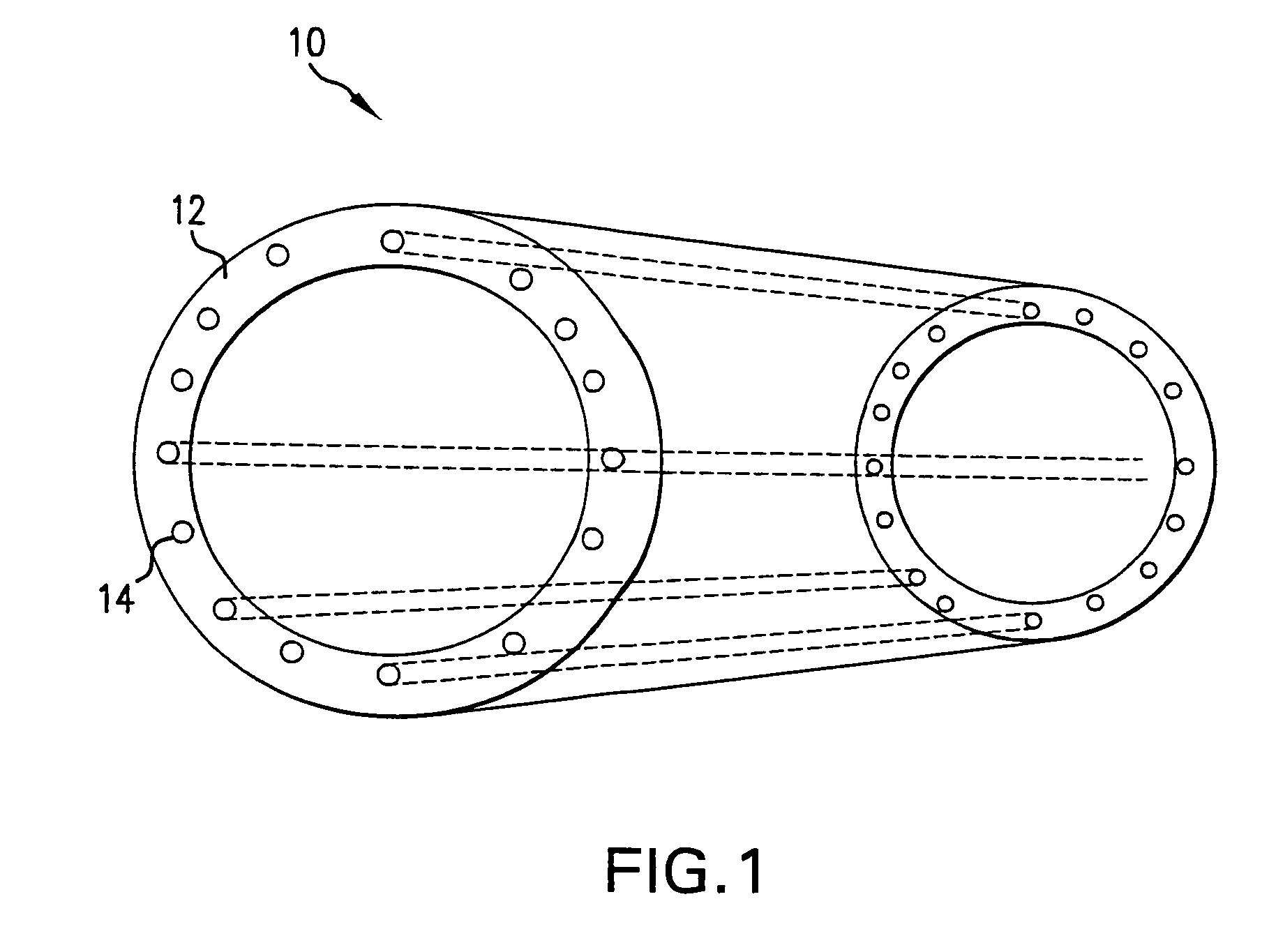
[0023]FIG. 1 shows a dryer 10 formed by a single shell 12 with a series of conduits 14 running along the length of the dryer. The dryer 10 is made of any suitable material, such as cast iron or stainless steel. These conduits 14 continuously carry a heating medium, such as steam, to heat the outside surface of the dryer, over which the paper web passes. By forming conduits within the shell, heat transfer occurs about the entire perimeter of the conduit, affording a maximum heat transfer surface. By way of example, a shell having a ¾ inch thickness can have conduits ¼ inch in diameter. The number of conduits is limited to maintain the shell's integrity.

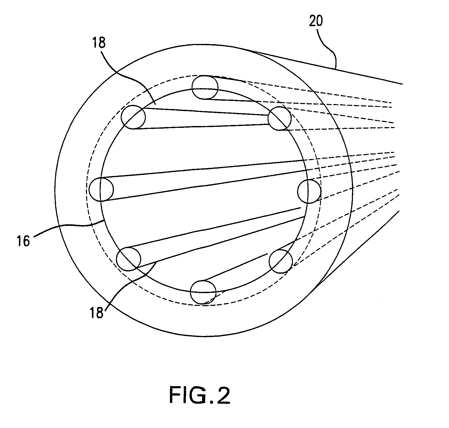
[0024]An alternative arrangement shown in FIG. 2 forms grooves within the inner surface 16 of the shell and places conduits 18 within the groove. The grooves can have a depth equal to half the diameter of the conduits. A conduit inserted to a depth equal to its radius and placed side-to-side offers an increase of 54% in heat transfer s...


PUM

PropertyMeasurementUnit
thicknessaaaaaaaaaa
pressureaaaaaaaaaa
lengthaaaaaaaaaa

Abstract

A dryer uses conduits to carry a heating medium, such as steam, to heat the outer surface of the dryer. The volume of steam is successfully reduced to non-explosive levels and the shell need not be designed to prevent an explosion. Conduits may be formed through the shell itself or grooves may be formed on the inner surface of the shell, with the conduits retained within the grooves. Also, the conduits can be placed against the inside surface of the dryer and a material, such as zinc, can be filled in about the conduits. The material serves to both retain the conduits in place and thermally couple the conduits to the dryer to assure efficient heat transfer between the conduits and dryer. These modifications relieve the dryer from the Unfired Pressure Vessel classification to the classification of a piping assembly under ASA code regulations. This results in savings in operation safety, installation cost and operating costs due to the absence of costly inspections. Transportation costs are lowered by manufacturing a plurality of holding plates which would be transported to the location of use at which point the Yankee dryer will be constructed. It is contemplated that the plurality of holding plates would not require a shell surrounding the exterior of these holding plates. Additionally, the thermal gradient on the exterior of the Yankee dryer will be controlled through the use of a plurality of auxiliary supply and exhaust conduits.

Description

CROSS-REFERENCE TO RELATED APPLICATIONS[0001]This application claims benefit of provisional patent application Ser. No. 60 / 793,657, filed Apr. 21, 2006, and claims the priority of U.S. patent application Ser. No. 11 / 785,614, filed Apr. 19, 2007.FIELD OF THE INVENTION[0002]The present invention is directed to the field of cylindrical dryers generally used in the papermaking industry.BACKGROUND OF THE INVENTION[0003]Cylindrical dryers are used in the paper making process. Webs of paper are passed over heated cylindrical drums to remove moisture from the web. The large cylindrical dryers, often referred to as “Yankee Dryers,” must be continuously heated to maintain an elevated temperature during the paper making process.[0004]One type of Yankee dryer has an inner and outer shell. The space created between the inner and outer shell is fed with a heating medium, such as steam under pressure, to heat the outer surface of the dryer. The dryers are commonly made out of cast iron. A double s...

Claims


Application Information

Patent Timeline
Patent Type & Authority Patents(United States)
IPC IPC(8): F26B11/02
CPCF26B13/183
Inventor HAURIE, OSVALDO RICARDOHAURIE, RICHARD KENNETH
Owner HAURIE OSVALDO RICARDO
Why Eureka
Try Eureka