
Method for controlling a blood pump

a technology of rotating blood pump and rotating shaft, which is applied in the direction of heart stimulators, prostheses, therapy, etc., can solve the problems of thrombogenesis risk, impeller operation, risk of obstruction of blood system, etc., and achieve the effect of restricting the action of the blood pump

Active Publication Date: 2012-02-28
ABIOMED EURO
View PDF14 Cites 146 Cited by
  • Summary
  • Abstract
  • Description
  • Claims
  • Application Information

AI Technical Summary

Benefits of technology

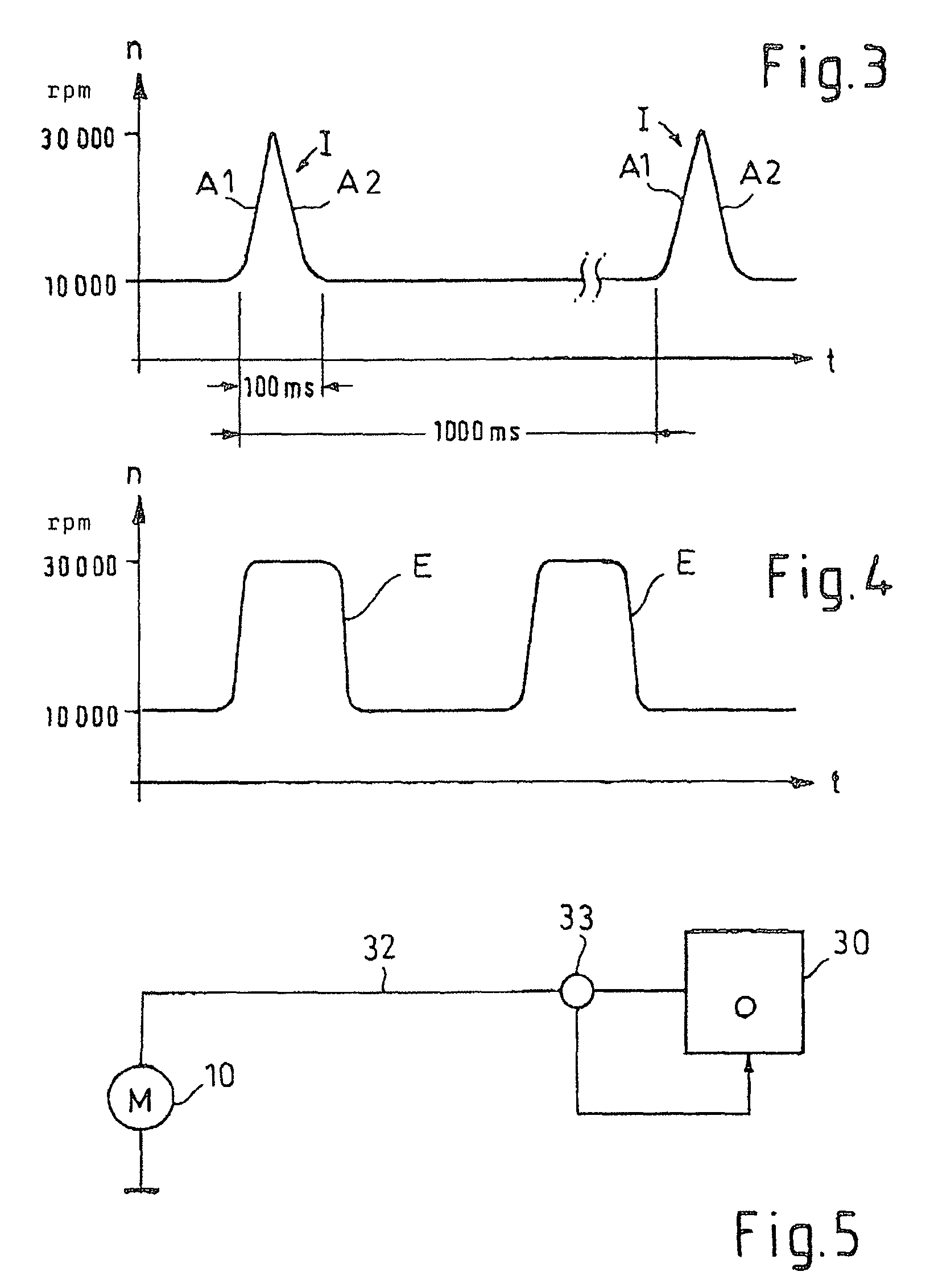
The invention provides a method for controlling the rotational speed of a rotary blood pump to ensure efficient blood conveyance and prevent thrombogenesis. The method involves alternating the pump at a low rotational speed and at the design speed for a short period of time. This allows for temporary operation below the design speed without causing any risk of blood clotting. The method also allows for controlling the volume flow and delivery rate without a continuous operation at the high design speed. The pump can be operated at a lower speed for a short time to prevent blood clotting, and the speed can be increased quickly to the design speed to avoid a buildup of blood clots. The method can be controlled by presetting an excitation frequency or by externally controlling the deceleration of the rotational speed. The invention also allows for synchronizing the pumping function of the heart with the pump's rotational speed.

Problems solved by technology

Flow detachments and turbulences involve the risk of thrombogenesis, wherein blood accumulates and gathers at the impeller or at other locations in the blood system.
This impairs the operation of the impeller.
Further, this involves the risk of obstructions in the blood system.

Method used


Image

  • Method for controlling a blood pump
  • Method for controlling a blood pump
  • Method for controlling a blood pump

Examples


Embodiment Construction

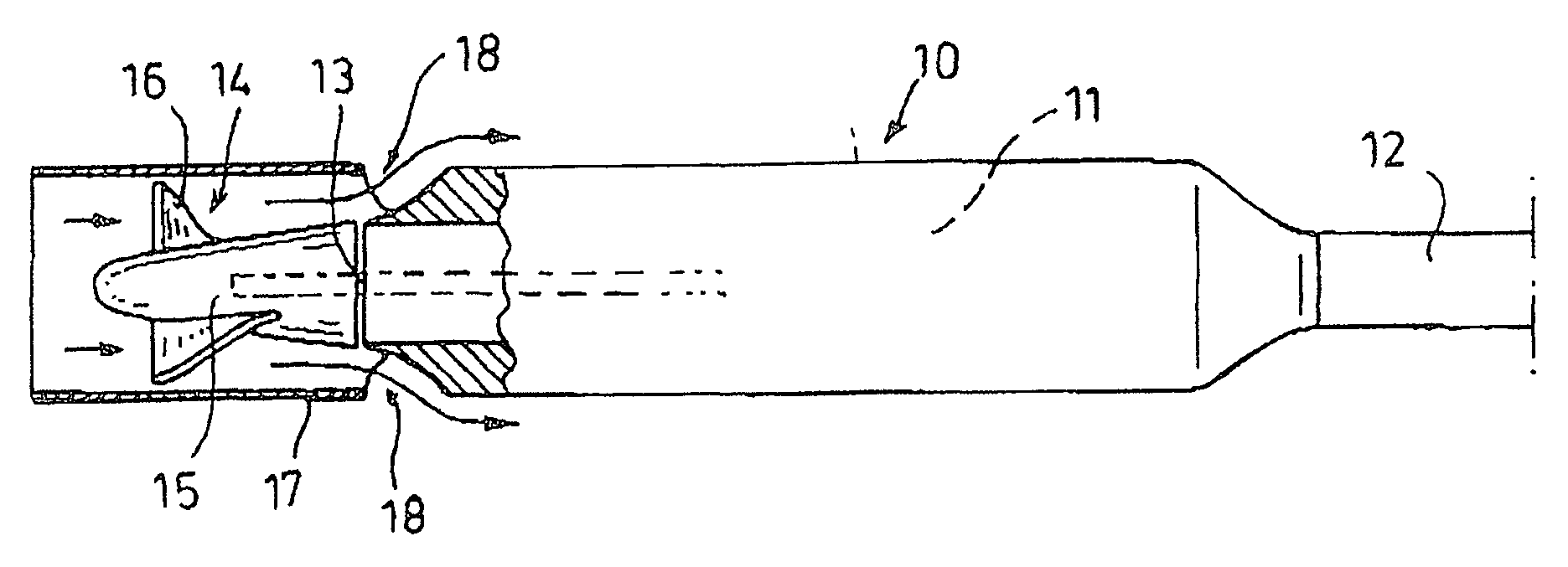
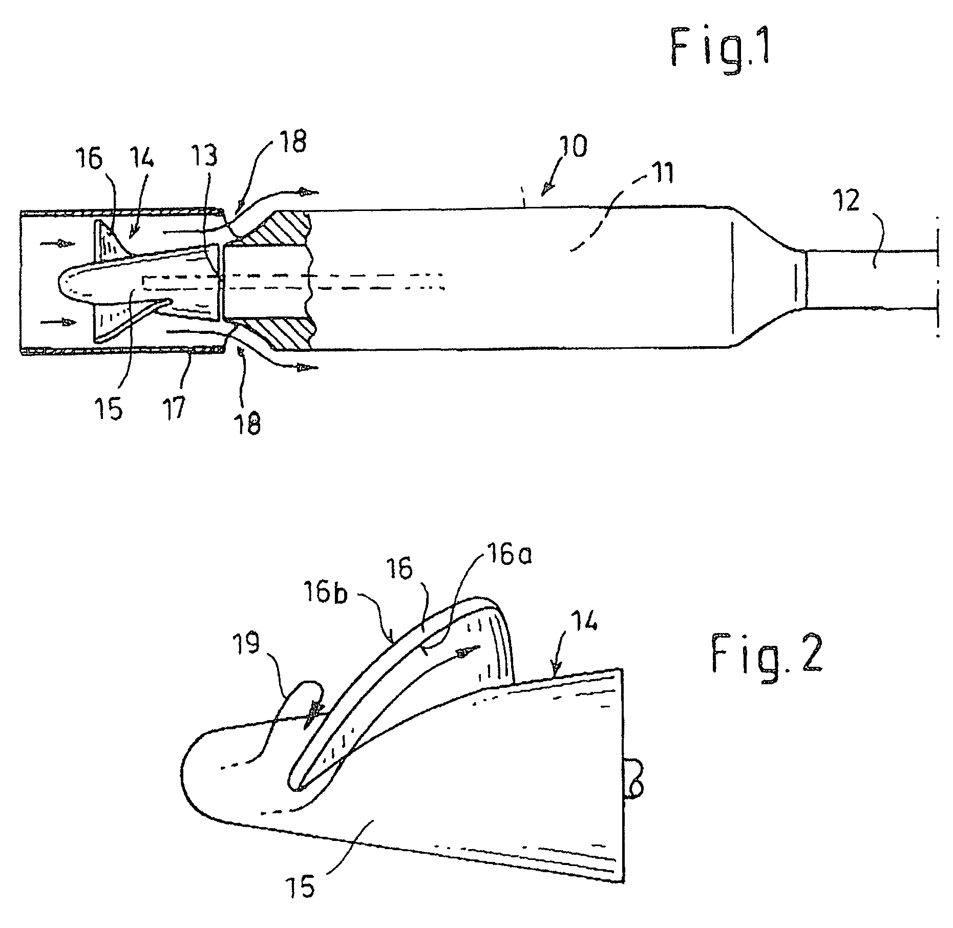
[0022]FIG. 1 shows a rotary blood pump 10 for supporting the heart function. Here, the blood pump is an intravascular pump whose maximum outer diameter is at no place larger than 7 mm. The blood pump may also be configured as an intracardiac blood pump which is inserted through an incision of the heart. Such a blood pump may have a somewhat larger diameter. Further, the pump may be placed paracardiacally (around the heart) and take blood via two incisions from a location in front of the heart or from the heart, and return the blood via the second incision behind the heart.

[0023]The blood pump 10 comprises an elongate cylindrical motor 11 whose proximal end has connected therewith a flexible catheter 12. Electrical conduits (not shown) extend through the catheter 12 to a controller.

[0024]A shaft 13 of the motor 11 carries an impeller 14 with a hub 15 tapering towards a distal end thereof, with helical blades 16 extending from said hub 15.

[0025]The impeller 14 is surrounded by an elon...


PUM


Abstract

A blood pump is temporarily operated at a low rotational speed lying below a design rotational speed. This involves a risk of thrombogenesis since flow detachments may occur at blades of an impeller of the rotary blood pump. For eliminating deposits at said impeller, the rotational speed of said pump is temporarily increased to the design rotational speed. Alternatively, said pump alternately operates at said design rotational speed and a low rotational speed, and this pulsed operation is synchronized with the heart rate.

Description

RELATED APPLICATIONS[0001]This application is a U.S. national phase of PCT / EP06 / 061582, filed Apr. 13, 2006, which claims priority from German Application No. 102005017546.5, filed Apr. 16, 2005.BACKGROUND OF THE INVENTION[0002]The invention relates to a method for controlling the rotational speed of a rotary blood pump having a design rotational speed at which minimal detachment and swirling of the blood flow occur.[0003]In EP 0 961 621 B1 (Impella) an intravascular blood pump is described which is inserted through the vascular system into the body and placed in the heart or at any other location where blood is intended to be pumped. The blood pump comprises a housing with a diameter of 5.4 to 6.4 mm which defines the stator of a motor. A rotor is connected with an impeller which rotates in a pump ring. This very small blood pump has a relatively high rotational speed in the range of 30,000 rpm.[0004]In EP 0 925 080 B1 (Impella) a method for controlling a rotational speed of a bloo...

Claims


Application Information

Patent Timeline
Patent Type & Authority Patents(United States)
IPC IPC(8): A61M1/12
CPCA61M1/125A61M1/101A61M2205/3334A61M60/546A61M60/419A61M60/178A61M60/806A61M60/191A61M60/226A61M60/569A61M60/577A61M60/148
Inventor SIESS, THORSTENDAMEN, RAINER
Owner ABIOMED EURO
Learn More