
Solar powered smart ventilation system

a smart ventilation and solar energy technology, applied in ventilation systems, lighting and heating apparatus, heating types, etc., can solve the problems of increasing the cost of such energy consumption, affecting the comfort of living environment, and causing the castle to feel more like a dungeon, so as to achieve the effect of quick and easy installation and requiring a relatively small amount of energy to run

Active Publication Date: 2012-02-28
THE SECURECASE
View PDF20 Cites 26 Cited by
  • Summary
  • Abstract
  • Description
  • Claims
  • Application Information

AI Technical Summary

Benefits of technology

"The present invention is a ventilation system that can be easily installed and requires less energy to run. It is designed to be modular, meaning it can be customized and combined in different ways to meet different needs."

Problems solved by technology

Due environmental and economic concerns, maintaining a comfortable living environment has become a challenge.
We need to consume energy to maintain a suitable living standard, yet consumption of such energy is becoming more expensive and environmentally unfriendly.
The challenge arises in trying to find alternative sources of energy while minimizing the use of conventional energy sources.
However, if comfortable living conditions cannot be maintained, his castle may feel more like a dungeon.
However, running the air conditioner, particularly central air, is extremely costly as it requires a lot of energy consumption.
These units tend to be heavy, loud, and at times, no better than traditional fans.

Method used


Image

  • Solar powered smart ventilation system
  • Solar powered smart ventilation system
  • Solar powered smart ventilation system

Examples


Embodiment Construction

[0014]The detailed description set forth below in connection with the appended drawings is intended as a description of presently-preferred embodiments of the invention and is not intended to represent the only forms in which the present invention may be constructed or utilized. The description sets forth the functions and the sequence of steps for constructing and operating the invention in connection with the illustrated embodiments. However, it is to be understood that the same or equivalent functions and sequences may be accomplished by different embodiments that are also intended to be encompassed within the spirit and scope of the invention.

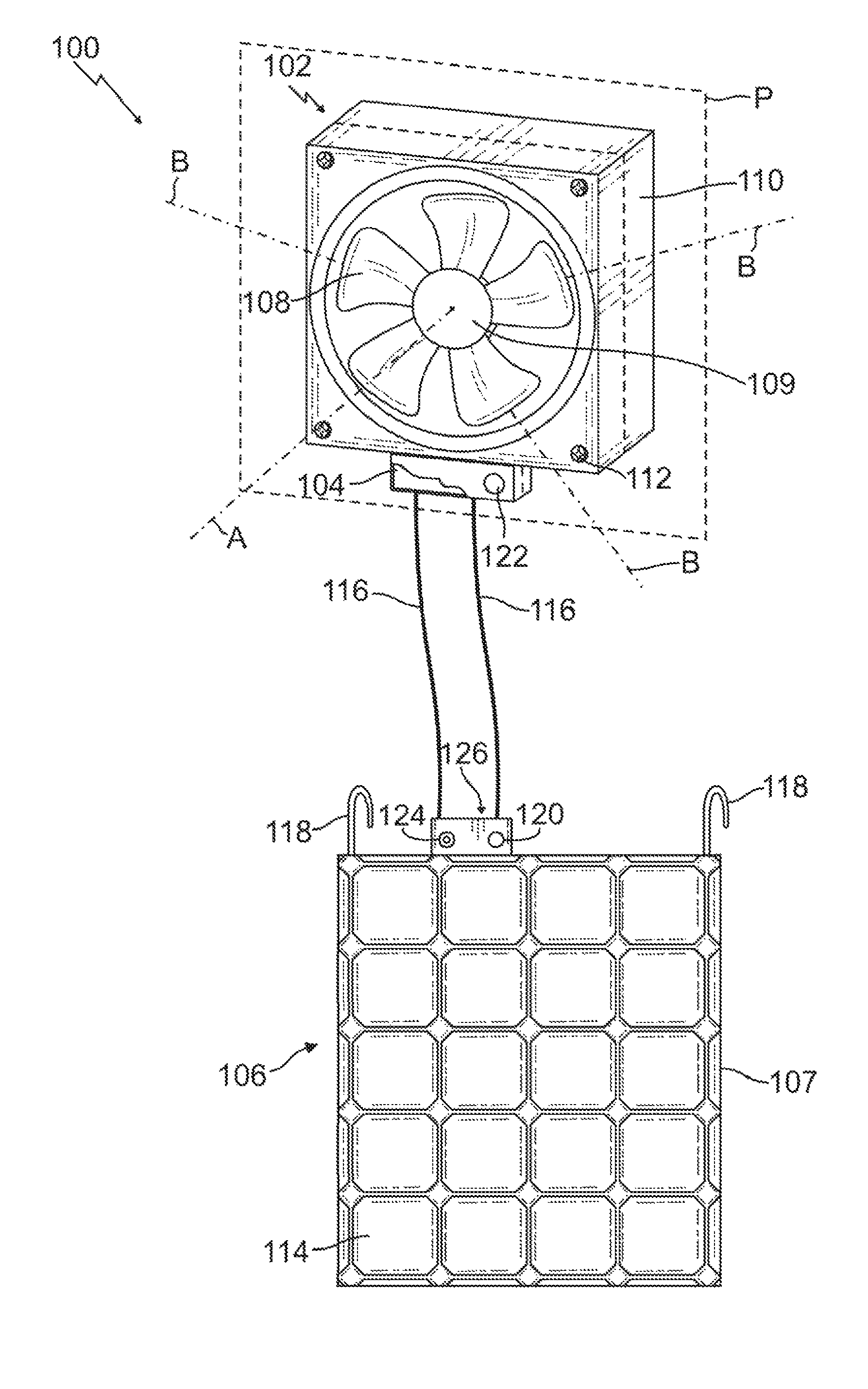
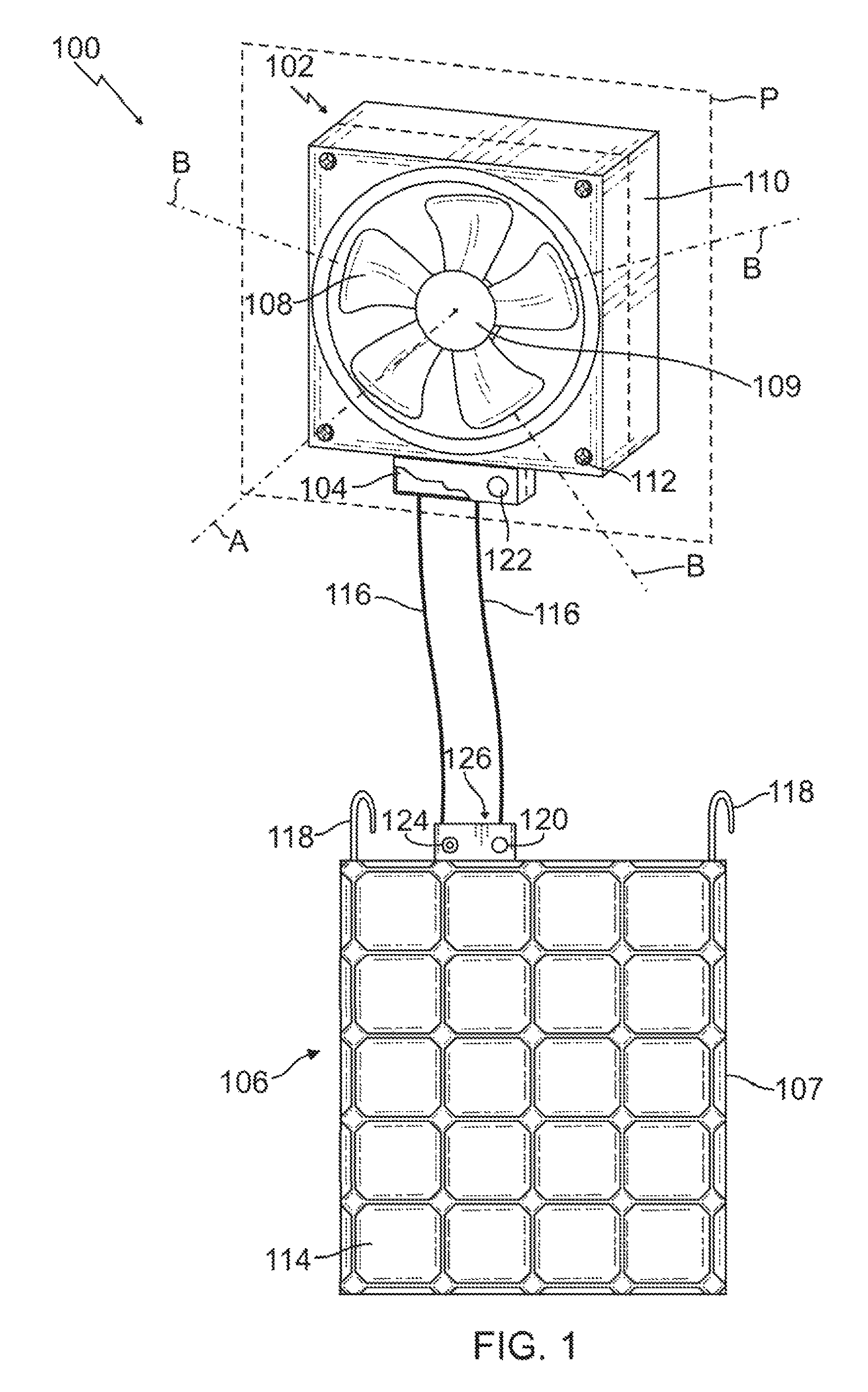
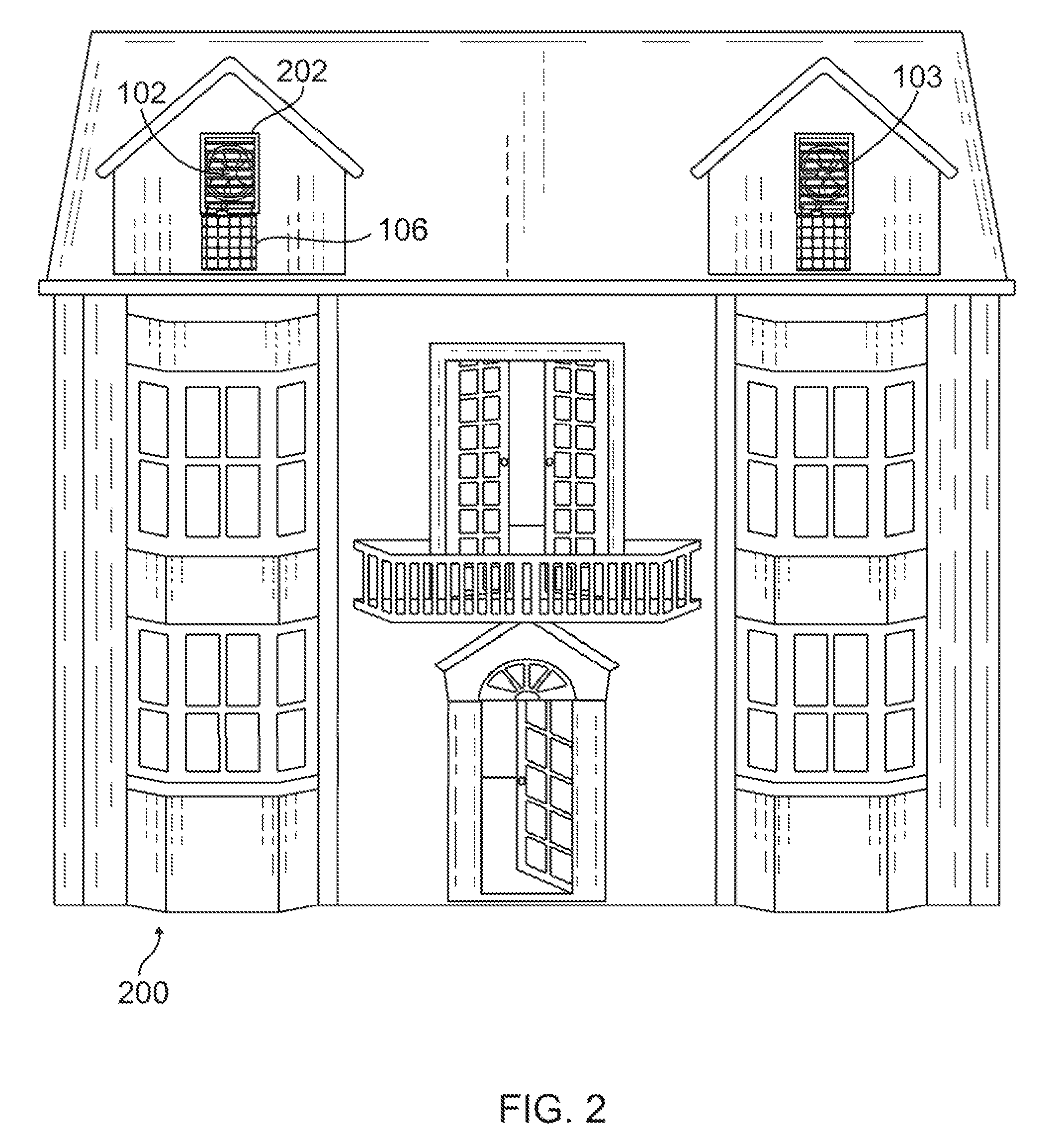
[0015]With reference to FIG. 1, the ventilation system 100 comprises a means for generating air flow, such as a fan 102, to bring cool air into the building 200 or exhaust hot air out of the building 200, a rechargeable battery 104 to power the fan 102 in the absence of an alternative energy source, and an alternative energy harnessing devi...


PUM


Abstract

A ventilation system comprising a fan to bring air into a building or exhaust air out of the building, a rechargeable battery to power the fan in the absence of an alternative energy source, and an alternative energy harnessing device to power the fan and to recharge the rechargeable battery in the presence of an alternative energy source. A sensor may be operatively connected to a controller or logic circuit to measure environmental factors, wherein the controller utilizes the measured environmental condition to select the power source with which to activate the fan. The ventilation system is configured to be a modular device with versatile fasteners for easy installment in windows or attics without the need for modification of the building, such as cutting holes.

Description

CROSS-REFERENCE[0001]This patent application claims the benefit of U.S. Provisional Patent Application Ser. No. 61 / 235,432, entitled “Solar Powered Smart Ventilation System,” filed Aug. 20, 2009, which application is incorporated in its entirety here by this reference.BACKGROUND OF THE INVENTION[0002]1. Technical Field[0003]This invention relates to environmentally-friendly air ventilation systems to help control air temperatures of an enclosed area.[0004]2. Background Art[0005]Due environmental and economic concerns, maintaining a comfortable living environment has become a challenge. We need to consume energy to maintain a suitable living standard, yet consumption of such energy is becoming more expensive and environmentally unfriendly. The challenge arises in trying to find alternative sources of energy while minimizing the use of conventional energy sources.[0006]It has been said that a man's home is his castle. However, if comfortable living conditions cannot be maintained, his...

Claims


Application Information

Patent Timeline
Patent Type & Authority Patents(United States)
IPC IPC(8): F24F7/00F24F11/76
CPCF24F7/06F24F11/0001H02S20/20F24F7/007F24F13/00H01L31/042F24F11/053F24F11/0012F24F2005/0067F24F2011/0013F24F2011/0049F24F2007/003Y02B10/24Y02B10/20F24F11/30F24F2110/10F24F2110/12F24F2130/20F24F11/76Y02A30/272Y02E10/50Y02B10/10F24F11/77F24F11/46F24F11/63F24F2007/0025
Inventor CISLO, DANIEL M.
Owner THE SECURECASE
Learn More