Guides for an extendable harvesting header

a technology of headers and guides, which is applied in the direction of mowers, agriculture tools and machines, etc., can solve the problems of limited vertical range of the movable headers, dirt is scooped in front of the headers, and metal-on-metal contact limits the lifetime of the guides, so as to reduce the effects of wear, minimise vertical clearance, and improve the stability of the header table during operation

Active Publication Date: 2012-02-28
BLUE LEAF I P INC
View PDF19 Cites 1 Cited by
  • Summary
  • Abstract
  • Description
  • Claims
  • Application Information

AI Technical Summary

Benefits of technology

[0011]The present invention has some important advantages. The inclined side wall provides for a fixed position of the cutterbar table with no clearance between the member and the slide surface of the telescopic assembly. Consequently, the lateral vibrations induced by the reciprocating cutterbar will not result in lateral movement of the table to the header frame. The header is much more stable and works more quietly. This also reduces the wear between the telescopic members. A single inclined wall would suffice, but a pair of inclined walls is preferable, giving the telescopic member an overall V-shape.
[0013]The guide means may comprise wear parts that can be replaced. The use of replaceable wear parts reduces the effects of wear on the frame and the movable table. They may include caps or strips on the front end of the telescopic assembly. Furthermore, the guides may be adjusted, e.g. by screws, so as to compensate for wear and take away the possibility for lateral displacement of the movable table. The adjustment can also be used to minimise the vertical clearance between the inner and outer telescopic members. This improves the stability of the header table during operation.
[0014]A further advantage is that the wear guides of the present invention have no parts sticking out of the bottom of the header, hereby preserving the minimum available stubble height.

Problems solved by technology

A problem associated with these is the metal-on-metal contact limiting the lifetime of the guides.
Using replaceable metal wear blocks in the front of the header is known, but a problem with these is that dirt is scooped in front of the header due to the location of the wear blocks.
Furthermore, the vertical range of the movable header is limited by the extra space taken by the wear blocks.
Another problem with current U-shaped or rectangular guides is the lateral movement that is caused by the side movement of the knives.
This limits the lifetime of the header considerably.

Method used


Image

  • Guides for an extendable harvesting header
  • Guides for an extendable harvesting header
  • Guides for an extendable harvesting header

Examples


Embodiment Construction

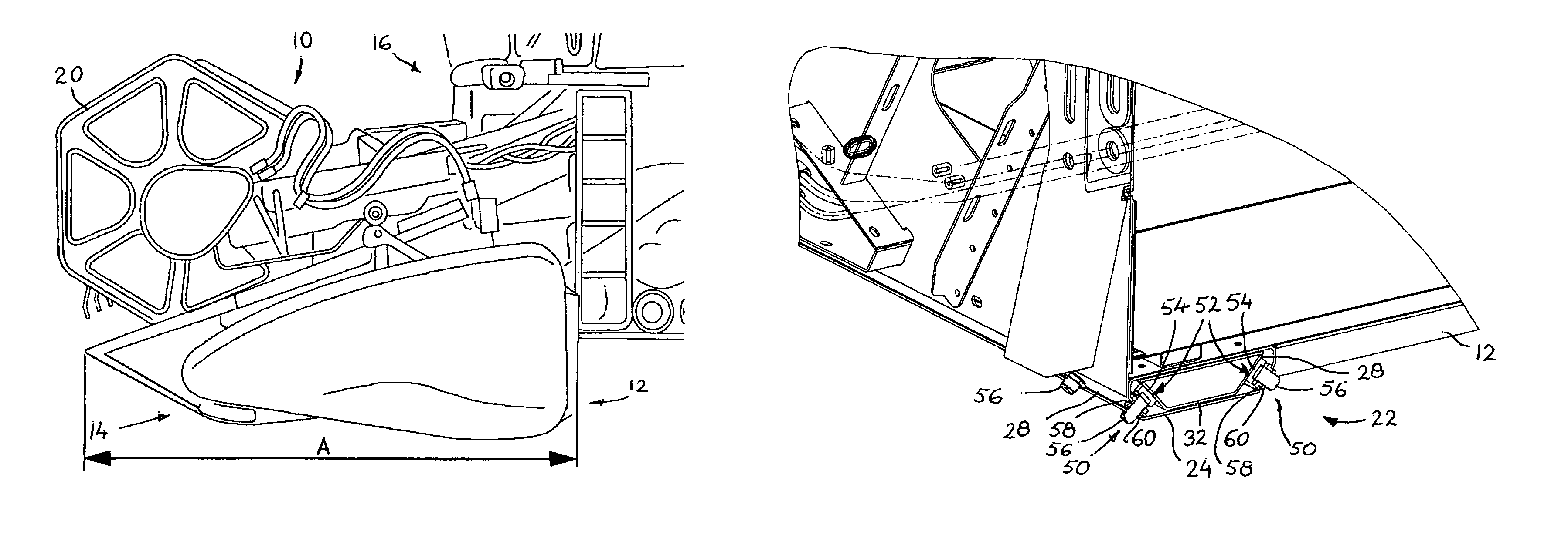
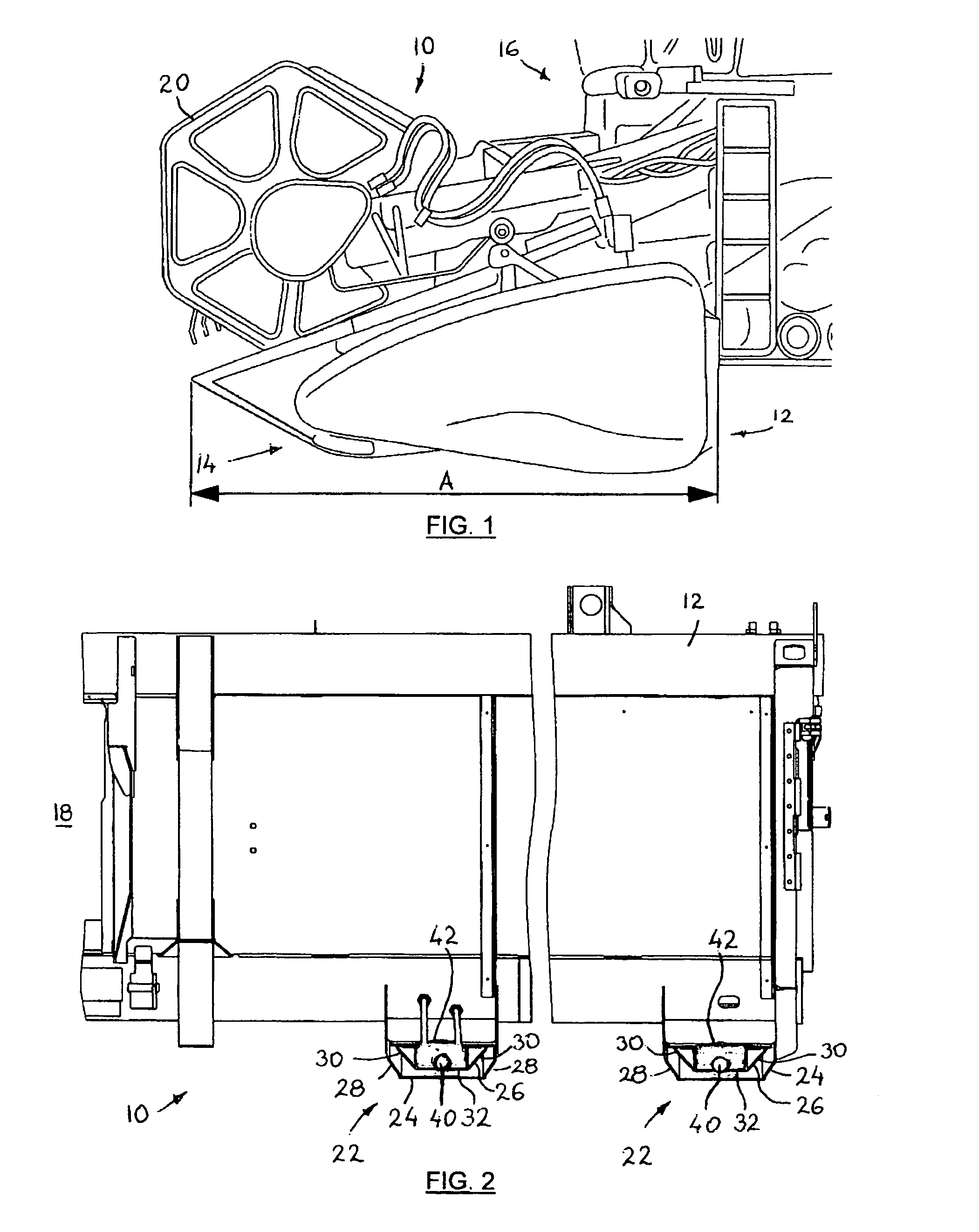
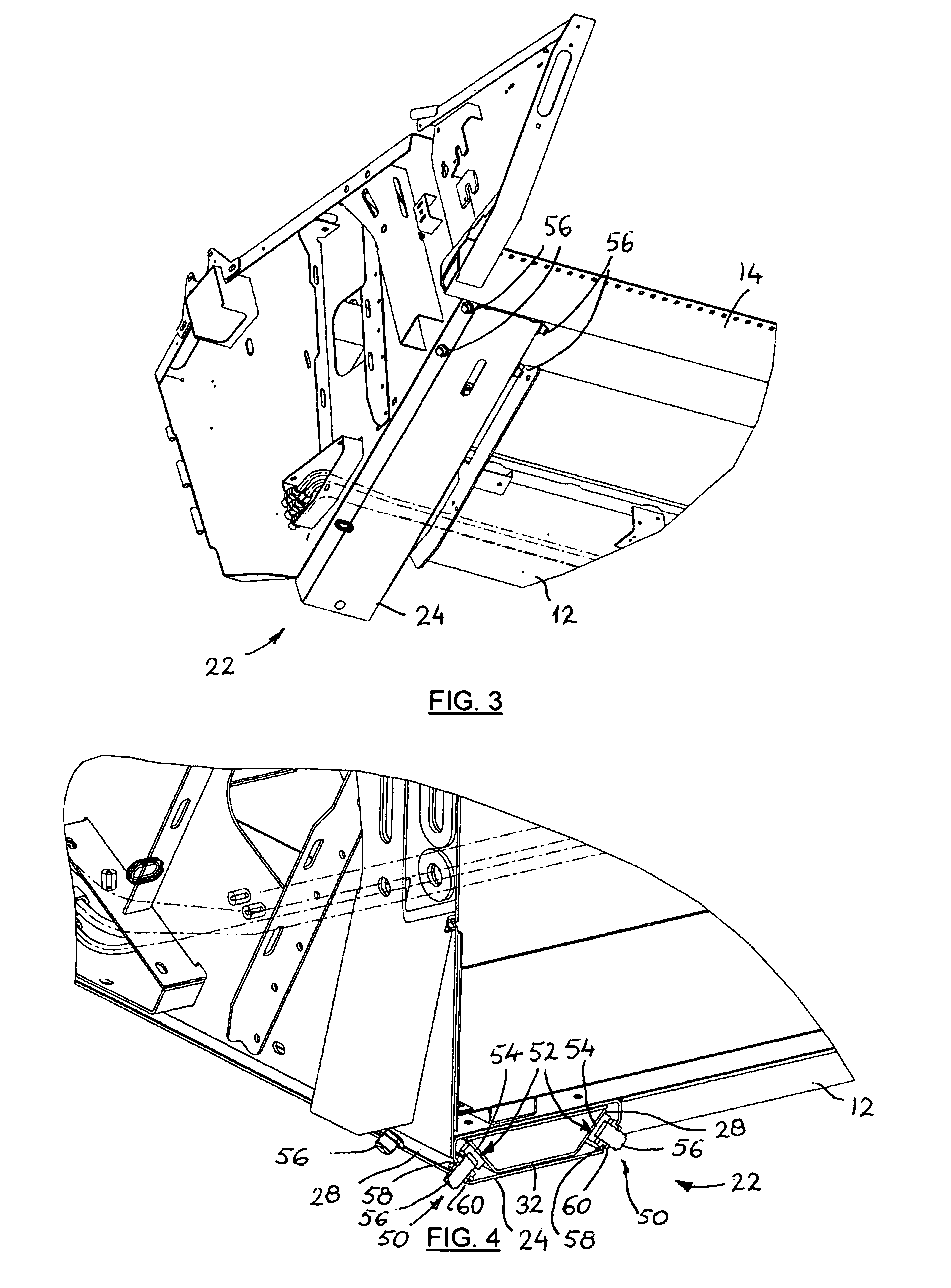
[0024]FIGS. 1 to 6 illustrate an extendable header 10 comprising a main frame 12 and a movable cutterbar table 14. The main frame 12 is releasably attached to an elevator of a combine harvester 16 and supports a transverse auger (not shown), which can be rotated to transport crop from the cutterbar table 14 to a central outlet opening 18 adjacent the elevator. The cutterbar table 14 comprises a cutterbar having a range of knives (not shown), which are reciprocated by an appropriate cutterbar drive (not shown) for cutting standing crop as the combine harvester 16 is travelled over a field. The header frame 12 is provided with a reel 20, which extends the full width of the header and can be rotated to guide the standing crop to the cutterbar table 14 and the cut crop to the transverse auger. The header 10 incorporates an embodiment of an improved guidance of the movable cutterbar table 14 according to the present invention.

[0025]The movable table 14 of the harvesting header 10 is conn...


PUM


Abstract

An header of the extendable type comprises a main frame and an extendable cutterbar table, which is mounted to the main frame by means of telescopic assemblies comprising an inner member mounted for sliding movement inside an outer member. One of the inner and outer members has longitudinal, inclined side walls that are engaged by inclined slide surfaces of guide means connected to a wall of the other of said outer and inner members, opposite said inclined side wall.

Description

CROSS REFERENCE TO RELATED APPLICATIONS[0001]This Patent Application claims priority under 35 U.S.C. §119 to EP 08.159.966.4, filed on Jul. 8, 2008 titled, “Guides for an Extendable Harvesting Header” and having Bart Moutton, Mateusz Rajca and Danny A.H. Descheemaecker as inventors. The full disclosure of EP 08.159.966.4 is hereby fully incorporated herein by reference.FIELD OF THE INVENTION[0002]The present invention relates to guides for the movable cutterbar table of an extendable header for a harvesting machine.BACKGROUND OF THE INVENTION[0003]Typically, a header for a harvesting machine includes a cutterbar which is operable to cut standing crop as the machine moves forward and a rotatable reel which carries tines to engage the standing crop and sweep it towards the cutterbar for cutting and then carry the cut material towards an auger before releasing it. The auger usually consolidates the cut crop material centrally of the header before it is passed on to an elevator and ther...

Claims


Application Information

Patent Timeline
Patent Type & Authority Patents(United States)
IPC IPC(8): A01D67/00
CPCA01D41/148
Inventor MOUTTON, BARTRAJCA, MATEUSZDESCHEEMAECKER, DANNY A. H.
Owner BLUE LEAF I P INC
Why Eureka
Try Eureka