
Glass substrate for magnetic disk and manufacturing method of the same

a technology of glass substrate and magnetic disk, which is applied in the direction of magnetic materials for record carriers, manufacturing tools, instruments, etc., can solve the problems of heavy load on the magnetic disk

Active Publication Date: 2012-02-21
HOYA CORP
View PDF15 Cites 8 Cited by
  • Summary
  • Abstract
  • Description
  • Claims
  • Application Information

AI Technical Summary

Benefits of technology

[0087]First, melted alumino silicate glass was formed in the shape of a disk by direct press using an upper die, lower die and barrel die, and plate-shaped amorphous glass was obtained. Next, both main surfaces of the plate-shaped glass underwent lapping processing, and a disk-shaped glass base material was obtained. Then, a hole portion was formed at the center of the glass base material using a diamond cutter, and a disk-shaped glass substrate was obtained (coring). In addition, in the used alumino silicate glass, main components were SiO2: 70 percent by mass, Al2O3: 10 percent by mass., Li2O: 5 percent by mass, Na2O: 7 percent by mass, ZrO2: 8 percent by mass.
[0088]Next, end faces of the glass substrate underwent mirror-surface polishing by a brush polishing method. At this time, used as the polishing grains was slurry (free polishing grains) containing cerium dioxide polishing grains. Further, the inner circumferential end portion underwent mirror-surface polishing by a magnetic polishing method. Then, the glass substrate subjected to the mirror-surface polishing step was rinsed by water. By this means, the diameter of the glass substrate was 65 mm, and the substrate for use in a 2.5-inch magnetic disk was prepared.
[0089]Next, the both main surfaces of the obtained glass substrate underwent lapping processing as in the above-mentioned lapping. Then, as the main-surface polishing step, the first polishing step was applied. Used as a polishing agent were cerium dioxide polishing grains. Then, the glass substrate subjected to the first polishing step was immersed sequentially in washing tanks respectively of a natural detergent, pure water (1), pure water (2), IPA (isopropyl alcohol) and IPA (steam dry) and washed.
[0090]Then, the both main surfaces of the obtained glass substrate underwent the second polishing step to finish the main surfaces in mirror surface form. Used as a polishing agent were cerium dioxide polishing grains finer than the cerium dioxide polishing grains used in the first polishing step. Then, the glass substrate subjected to the second polishing step was immersed sequentially in washing tanks respectively of a natural detergent (1), natural detergent (2), pure water (1), pure water (2), IPA (isopropyl alcohol) and IPA (steam dry) and washed. In addition, ultrasonic waves were applied to each washing tank.
[0091]Next, the glass substrate subjected to the above-mentioned lapping steps and polishing steps underwent chemical reinforcement. The chemical reinforcement was performed by preparing a chemical reinforcement solution of a composition that potassium nitrate:sodium nitrate=8:2 in weight ratio, heating the chemical reinforcement solution to 400° C., and immersing the washed glass substrate in the solution for about 4 hours. Thus, by immersing and treating in / with the chemical reinforcement solution, Li ions and Na ions in the surface layer of the glass substrate were respectively replaced with Na ions and K ions in the chemical reinforcement solution, and the surface layer of the glass substrate was reinforced. At this point, the thickness of the compressive stress layer was 114 μm.
[0092]Such a glass substrate was immersed in a water tank of 20° C. for quenching, and kept for about 10 minutes. The quenched glass substrate was immersed in concentrated sulfuric acid heated to about 40° C. and washed. Further, the glass substrate subjected to sulfuric acid cleaning was immersed sequentially in washing tanks respectively of pure water (1), pure water (2), IPA (isopropyl alcohol) and IPA (steam dry) and washed. In addition, ultrasonic waves were applied to each washing tank.

Problems solved by technology

However, when the magnetic disk is rotated at high speed in the HDD apparatus, a heavy load is imposed on the magnetic disk, and high strength (impact resistance) is required for the magnetic disk.

Method used


Image

  • Glass substrate for magnetic disk and manufacturing method of the same
  • Glass substrate for magnetic disk and manufacturing method of the same
  • Glass substrate for magnetic disk and manufacturing method of the same

Examples


embodiment 1

[0050]A glass substrate for a magnetic disk according to the invention is a glass substrate for a magnetic disk installed in a hard disk drive (HDD), etc. for example. The magnetic disk is, for example, a recording medium enabling high-density information signals to be recorded and reproduced by the perpendicular magnetic recording system. Further, the glass substrate for a magnetic disk is mainly used for 1.8-inch magnetic disks and 2.5-inch magnetic disks.

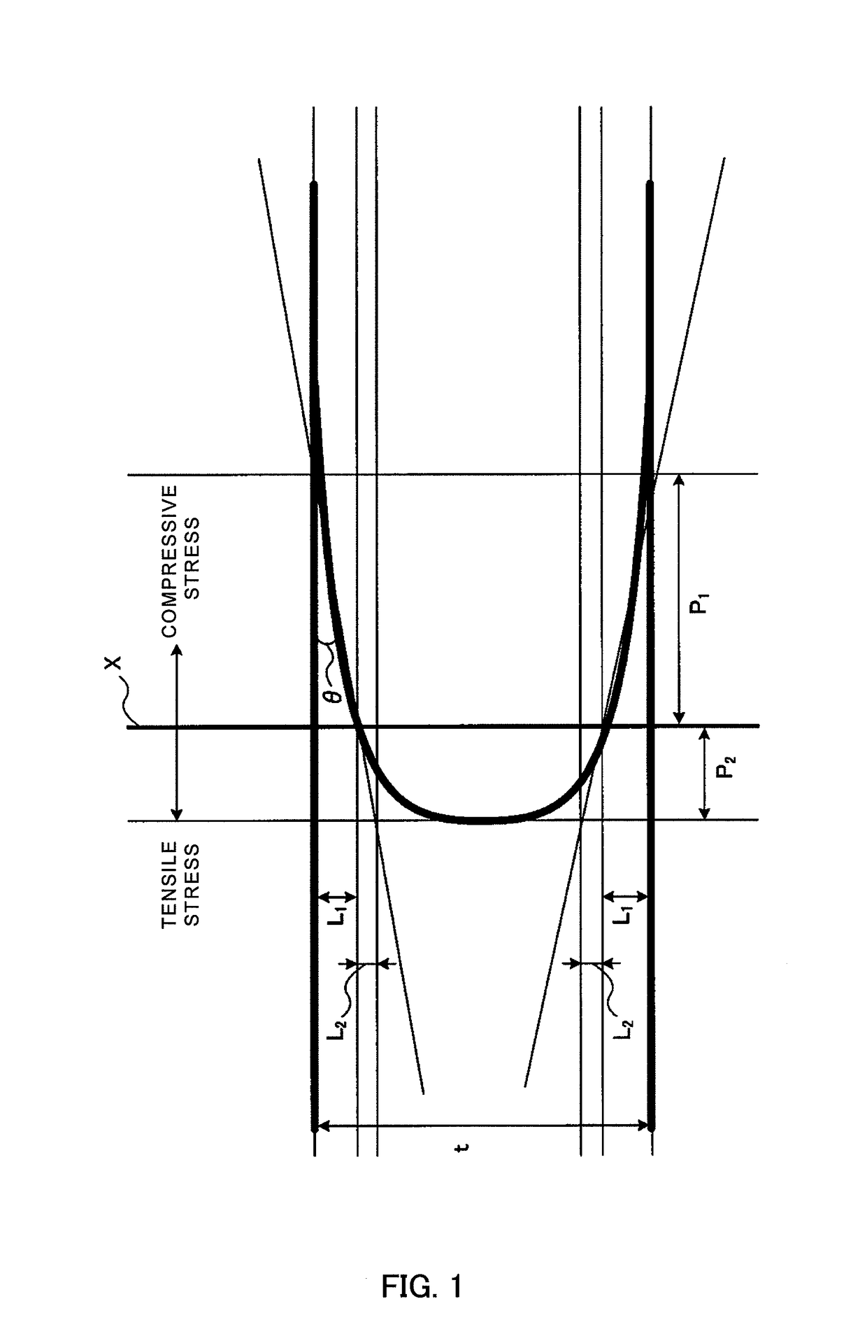
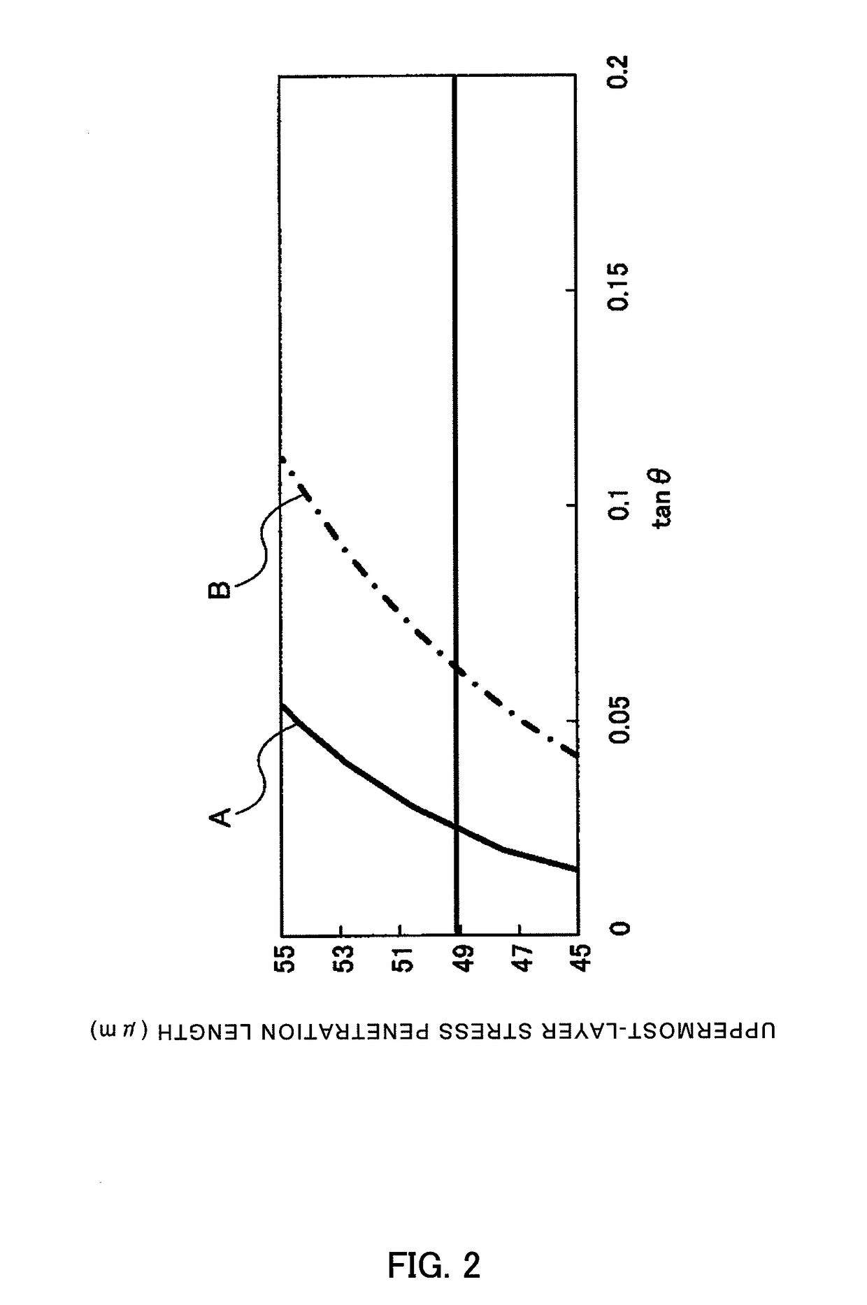
[0051]In the glass substrate for a magnetic disk according to the invention, the penetration length in the uppermost-portion stress layer on the main surface is 49.1 μm or less, and when it is assumed that an angle between the main surface and compressive stress in a stress profile by a Babinet compensator method is θ, a value y of {12·t·ln(tan θ)+(49.1 / t)} is the penetration length in the uppermost-portion stress layer or less. Therefore, the glass substrate is capable of meeting impact resistance higher than the currently requi...

example

[0087]First, melted alumino silicate glass was formed in the shape of a disk by direct press using an upper die, lower die and barrel die, and plate-shaped amorphous glass was obtained. Next, both main surfaces of the plate-shaped glass underwent lapping processing, and a disk-shaped glass base material was obtained. Then, a hole portion was formed at the center of the glass base material using a diamond cutter, and a disk-shaped glass substrate was obtained (coring). In addition, in the used alumino silicate glass, main components were SiO2: 70 percent by mass, Al2O3: 10 percent by mass., Li2O: 5 percent by mass, Na2O: 7 percent by mass, ZrO2: 8 percent by mass.

[0088]Next, end faces of the glass substrate underwent mirror-surface polishing by a brush polishing method. At this time, used as the polishing grains was slurry (free polishing grains) containing cerium dioxide polishing grains. Further, the inner circumferential end portion underwent mirror-surface polishing by a magnetic...

embodiment 2

[0098]In the method of manufacturing the glass substrate for a magnetic disk in this Embodiment, there are four aspects i.e. manufacturing method 1, manufacturing method 2, manufacturing method 3 and manufacturing method 4 as described below.

[Manufacturing Method 1 of the Glass Substrate for a Magnetic Disk]

[0099]Manufacturing method 1 of the glass substrate for a magnetic disk of this Embodiment is a manufacturing method of a glass substrate for a magnetic disk including a chemical reinforcement treatment step of immersing a disk-shaped glass substrate with a circular hole formed at its center portion in a chemical reinforcement treatment solution, causing ion exchange for replacing relatively small ions contained in the surface of the glass substrate with relatively large ions contained in the chemical reinforcement treatment solution, and thereby creating a compressive stress layer in the surface of the glass substrate, and is characterized in that the chemical reinforcement trea...


PUM

PropertyMeasurementUnit
surface roughness Raaaaaaaaaaa
lengthaaaaaaaaaa
surface roughness Raaaaaaaaaaa

Abstract

A glass substrate for a magnetic disk of the invention is a disk-shaped glass substrate for a magnetic disk where the substrate has a main surface and end face and is subjected to chemical reinforcement treatment, and is characterized in that the penetration length in the uppermost-portion stress layer on the main surface is 49.1 μm or less, and that assuming that an angle between the main surface and compressive stress in the stress profile by a Babinet compensator method is θ, a value y of {12·t·ln(tan θ)+(49.1 / t)} is the penetration length in the uppermost-portion stress layer or less.

Description

TECHNICAL FIELD[0001]The present invention relates to a glass substrate for a magnetic disk installed in a hard disk drive apparatus and a manufacturing method of the glass substrate.BACKGROUND ART[0002]There are magnetic disks as magnetic recording media installed in a hard disk drive apparatus (HDD apparatus). The magnetic disk is manufactured by depositing a NiP film on a metal substrate made of an aluminium-magnesium alloy or the like, or applying a magnetic layer and protective layer onto a glass substrate or ceramic substrate. Conventionally, as a substrate for the magnetic disk, aluminum alloy substrates have widely been used. In recent years, with reductions in size and thickness and high-density recording in the magnetic disk, glass substrates have been used which are more excellent in flatness of the surface and strength in the thin plate as compared with the aluminum alloy substrate (Japanese Laid-Open Patent Publication No. H09-27150).[0003]In recent years, in the magnet...

Claims


Application Information

Patent Timeline
Patent Type & Authority Patents(United States)
IPC IPC(8): C03C3/078G11B5/706B23Q3/00
CPCC03C21/002G11B5/8404G11B5/7315G11B5/73921
Inventor OSAKABE, KINOBUISONO, HIDEKIIWATA, KATSUYUKIEDA, SHINJITERADA, KENICHIRO
Owner HOYA CORP
Learn More