
Laser-ablatable elements and methods of use

a technology of laser and element, applied in the field of laser-ablatable elements, can solve the problems of limited plate production efficiency, slow and expensive use, and challenges the speed at which these flexographic printing plate precursors can be imaged, and achieve the effect of improving ablation efficiency and optimal ablation efficiency

Active Publication Date: 2012-02-14
MIRACLON CORP
View PDF21 Cites 41 Cited by
  • Summary
  • Abstract
  • Description
  • Claims
  • Application Information

AI Technical Summary

Benefits of technology

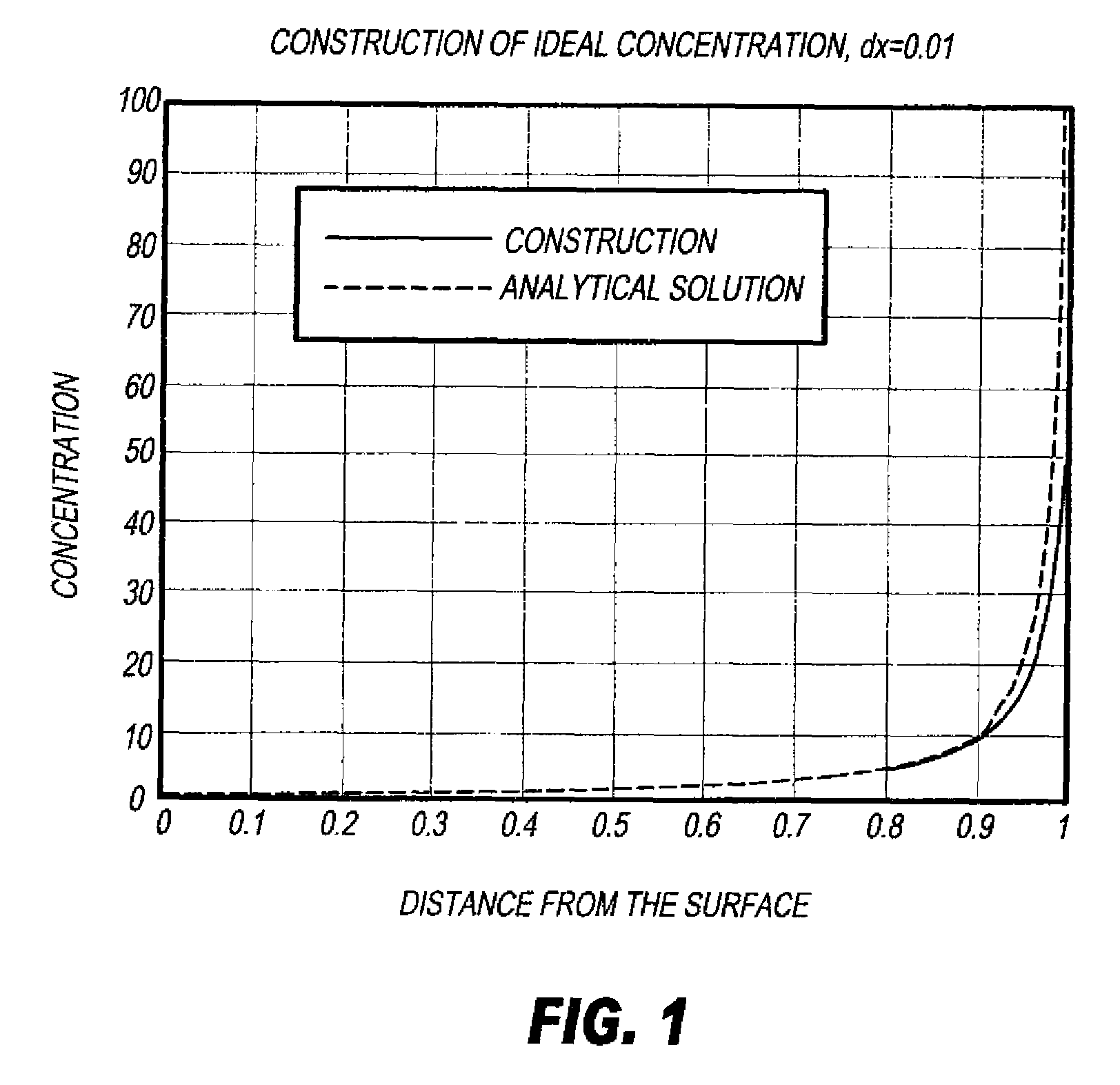
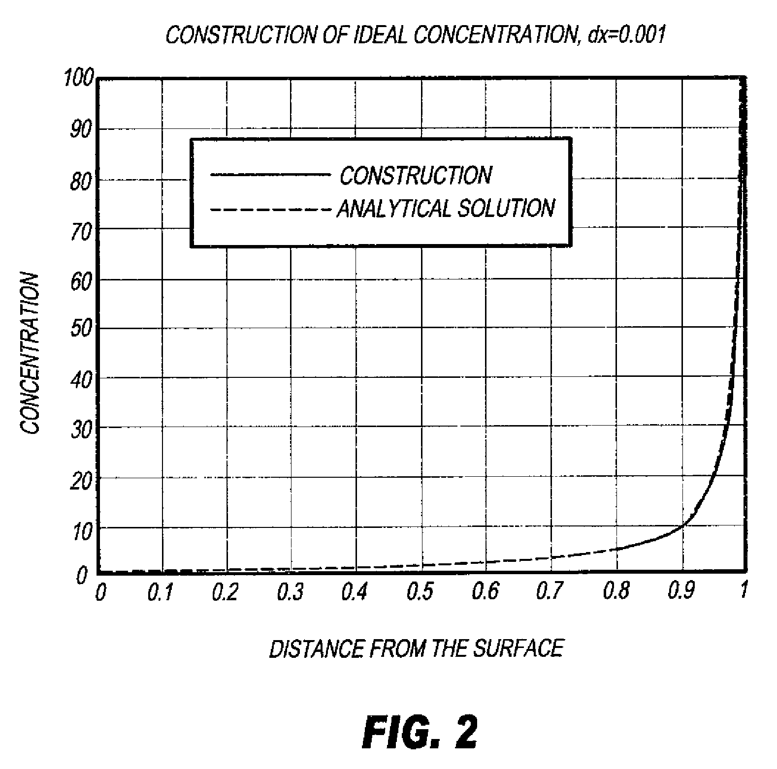
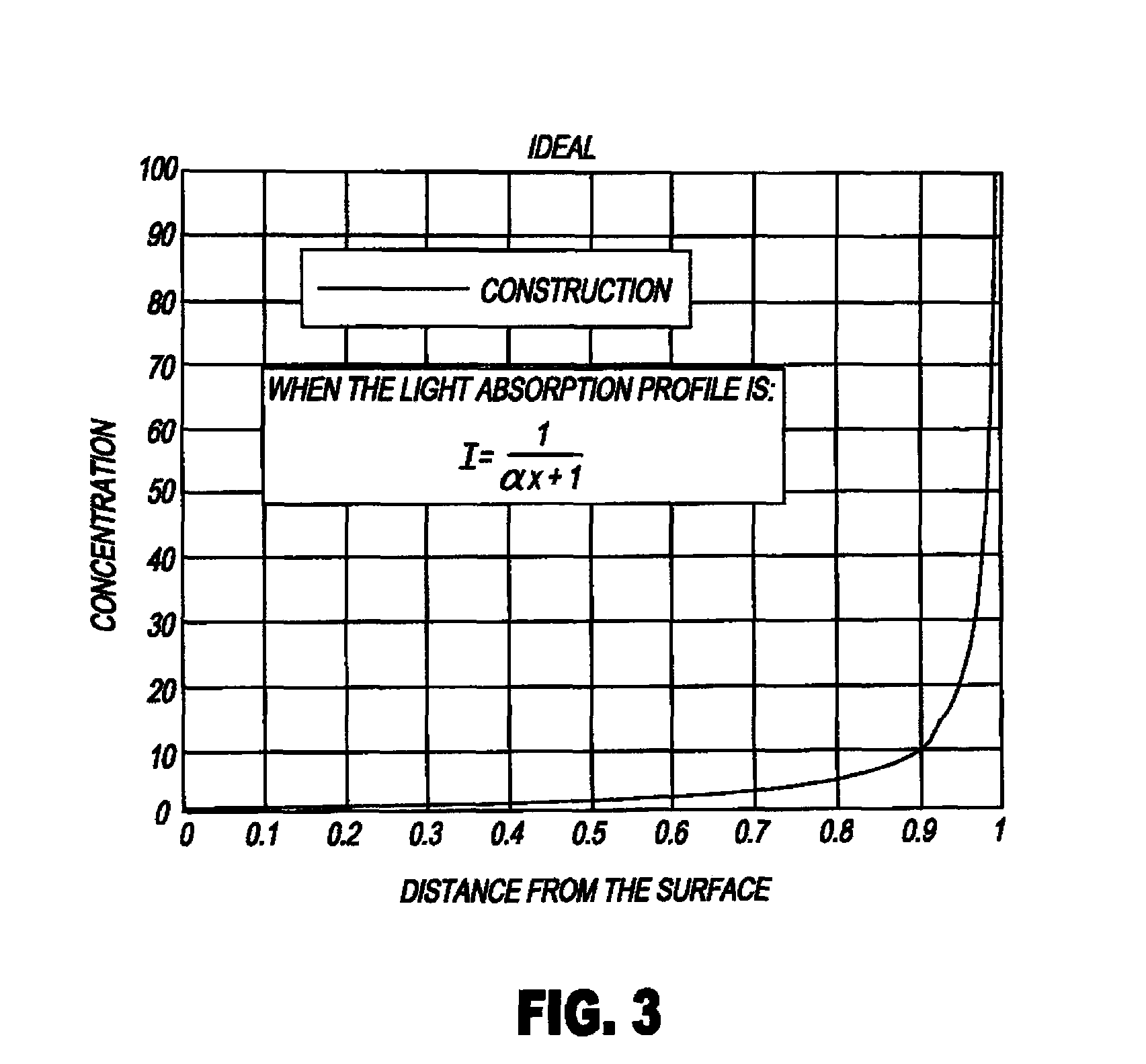
[0020]The present invention provides a number of advantages. The infrared radiation absorbing compound is distributed in the laser-ablatable relief-forming layer in a profile so that the compound concentration is greater at the bottom of the layer away from the imaging side. Thus, the concentration of the infrared radiation absorbing compound is lower at the top or imaging surface of the laser-ablatable, relief-forming layer. Applicants have discovered that this profile or arrangement of IR radiation absorbing compound concentration provides improved ablation efficiency as the ablated depth obtained in the laser-ablatable, relief-forming layer increases without excessive liquefaction of the laser ablatable materials in the layer.
[0021]This invention is particularly advantageous for providing optimal ablation efficiency without excessive liquefaction of the materials when imagewise exposure is carried out using pulsing lasers, that is, when the exposure energy is applied in a substantially adiabatic manner.

Problems solved by technology

In addition, the efficiency in producing plates is limited by the additional drying time of the developed plates that is required to remove the developing liquid and dry the plate.
However, the requirement of relief depths in excess of 500 μm challenges the speed at which these flexographic printing plate precursors can be imaged.
While they are generally slow and expensive to use and have poor beam resolution, they are used because of the attractions of direct thermal imaging.
These lasers provide better beam resolution, but are very expensive.
However, these systems suffer from poor engraving efficiency when it is desired to ablate several hundred microns into the element and no guidance is provided as to the optimal loading of IR absorbers with respect to the amount of resin or to the effect of concentration of the IR absorber on laser engraving efficiency.
When a low concentration of IR absorbing compounds is incorporated into the element, there is either not enough absorption of energy to cause ablation, or there is excessive liquefaction of the element with little ejection of material.
Even when ejection occurs, the presence of excess liquefaction, or viscous un-ejected material can be difficult to remove from the ablated plate.
This can also cause problems such as imprecise edges of the imaged features of the relief pattern and the adherence of molten polymer to the surfaces and / or sides of the relief pattern.
This ultimately will interfere with image feature quality and printing quality.
Further, when large amounts of liquid or viscous material are generated during the laser ablation and are ejected, this debris can stain the optical parts of the laser engraving apparatus, such as the lens, and causes problems with the apparatus.
When a high loading of IR absorbing compound is used, there is a decrease in the laser penetration depth due to the Beer-Lambert law of absorbance, and poor ablation efficiency.
Another disadvantage to high incorporation of the IR absorbing compounds is that many such compounds, including carbon black, also absorb in the UV region and thus would block any UV radiation that could be used to photochemically crosslink or cure the element composition.

Method used


Image

  • Laser-ablatable elements and methods of use
  • Laser-ablatable elements and methods of use
  • Laser-ablatable elements and methods of use

Examples


examples

[0157]The following components were used in preparing and carrying out the Examples:

[0158]PHMC represents polyhexamethylene carbonate diol, MW=2000 obtained from Sigma-Aldrich (St. Louis, Mo.).

[0159]Desmodur® N3300A is a hexamethylene diisocyanate based polyisocyanate obtained from Bayer Material Science (Pittsburgh, Pa.).

[0160]Mogul L is a carbon black obtained from Cabot Corporation (Billerica, Mass.).

[0161]Solsperse® 34750 is a 50 wt. % solution in ethyl acetate obtained from Lubrizol Limited (Manchester, UK).

Part A: Carbon Black Dispersion

[0162]Part A was prepared by mixing 494 g of PHMC with 60 grams of Mogul L and 46 g of Solsperse 34750, heating to 85° C. and milling using a Ross Mill equipped with a Cowles blade at 1200 rpm for 16 hours under vacuum to remove the ethyl acetate. The final concentration of the carbon black was 10.4 wt. % and the volume median particle size was 320 nm as determined using the Horiba particle size analyzer.

Melt A: Urethane Pre-Melt with 1 Wt. % C...

invention examples 1-3

[0166]Multi-sublayer laser-ablatable elements of this invention were prepared by casting a specified melt from TABLE I as the bottom layer into a 5″×5″ (12.7 cm×12.7 cm) Teflon mold, and covering it loosely to allow for evaporation of the acetone coating solvent. The sample was dried overnight at ambient temperature, followed by 24 hours at 70° C. Then, the next layer, again chosen from a melt in TABLE I, was cast over this bottom layer and the drying procedure repeated. Multilayer samples were built using this procedure. The final structures of the multilayer elements are shown in DIAGRAM I and TABLE II below. In DIAGRAM I and TABLE II, “CB” refers to carbon black at a particular dry weight %, and the thickness of each sub-layer is given in micrometers (μm).

invention example 4

[0172]A carbon black dispersion was prepared by mixing 75 g of Mogul L carbon black (Cabot) with 195 g of acetone and 30 g of Solsperse® 32000 (Avecia Pigments and Additives, Charlotte, N.C.) and the mixture was milled in an Eiger Mill at 4500 rpm for 2.5 hours. The resulting median particle size (volume average) was 0.129 μm, as measured using the Horiba particle size analyzer. A 2.4 g sample of this carbon black dispersion was added to 40 g of a 25 wt. % solution of cellulose nitrate (viscosity 5 / 6 sec, Hercules Powder Co., Wilmington, Del.) in acetone and stirred with a magnetic stirrer. The mixture was placed in a 3 inch (7.6 cm) square Teflon mold and covered with aluminum foil having 3 holes punched in it for slow solvent evaporation. The sample was dried for 24 hours in the mold at ambient temperature. The sides of the mold were removed and the sample element was dried for another 24 hours at ambient temperature to form the plate element.

[0173]A thin (5 μm) cross-section of t...


PUM

PropertyMeasurementUnit
thicknessaaaaaaaaaa
thicknessaaaaaaaaaa
depthaaaaaaaaaa

Abstract

A laser-ablatable element for direct laser engraving has a laser-ablatable, relief-forming layer that has a relief-image forming surface and a bottom surface. This relief-forming layer includes a laser-ablatable polymeric binder and an infrared radiation absorbing compound that is present at a concentration profile such that its concentration is greater near the bottom surface than the image-forming surface. This arrangement of the infrared radiation absorbing compound provides improved ablation efficiency, particularly when laser exposure is carried out adiabatically.

Description

FIELD OF THE INVENTION[0001]This invention relates to laser-ablatable elements that can be used to prepare relief images in flexographic printing plates. This invention also relates to a method of preparing these imageable elements. This invention further relates to a method of providing flexographic printing plates.BACKGROUND OF THE INVENTION[0002]Flexography is a method of printing that is commonly used for high-volume printing runs. It is usually employed for printing on a variety of substances particularly those that are soft and easily deformed, such as paper, paperboard stock, corrugated board, polymeric films, fabrics, plastic films, metal foils, and laminates. Course surfaces and stretchable polymeric films can be economically printed by the means of flexography.[0003]Flexographic printing plates are sometimes known as “relief printing plates” and are provided with raised relief images onto which ink is applied for application to the printing substance. The raised relief ima...

Claims


Application Information

Patent Timeline
Patent Type & Authority Patents(United States)
IPC IPC(8): G03F7/004G03F7/28G03F7/039
CPCB41C1/05B41M5/24Y10T428/269Y10S430/145B41N1/12Y10T428/31504
Inventor LANDRY-COLTRAIN, CHRISTINE J.BURBERRY, MITCHELL S.PERCHAK, DENNIS R.NG, KAM C.TUTT, LEE W.ROWLEY, LAWRENCE A.FRANKLIN, LINDA M.
Owner MIRACLON CORP
Learn More