
Use of coded excitation schemes in the detection and location of a target in a human body such as breast calcifications

a target detection and target technology, applied in the field of human target detection, can solve the problems of prohibitively expensive mri, poor contrast in mammographic images, and inaccessibility for all, and achieve the effect of facilitating the task, facilitating the adaptation to different physical situations, and facilitating the maintenance of acoustic coupling with the body

Inactive Publication Date: 2012-02-07
QUANTASON
View PDF3 Cites 12 Cited by
  • Summary
  • Abstract
  • Description
  • Claims
  • Application Information

AI Technical Summary

Benefits of technology

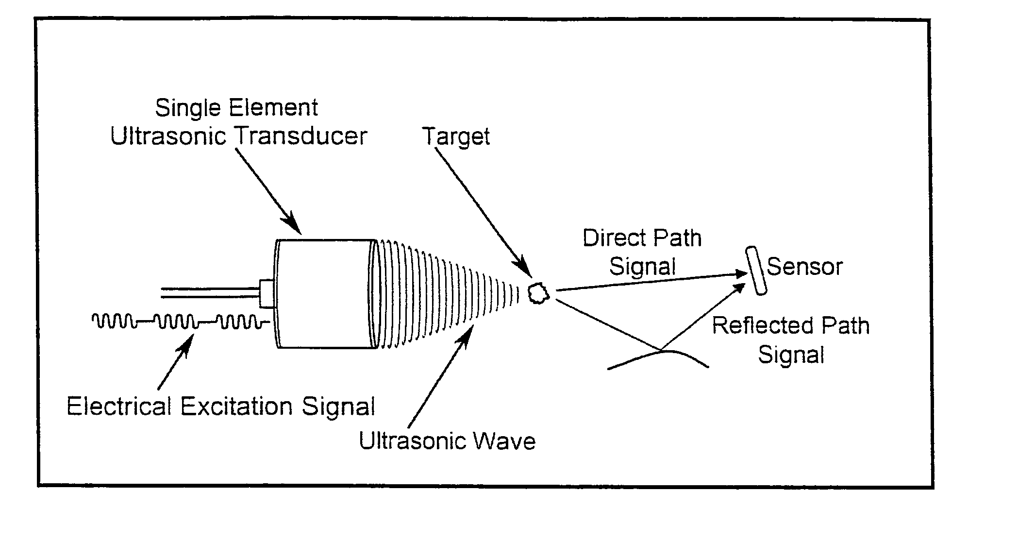
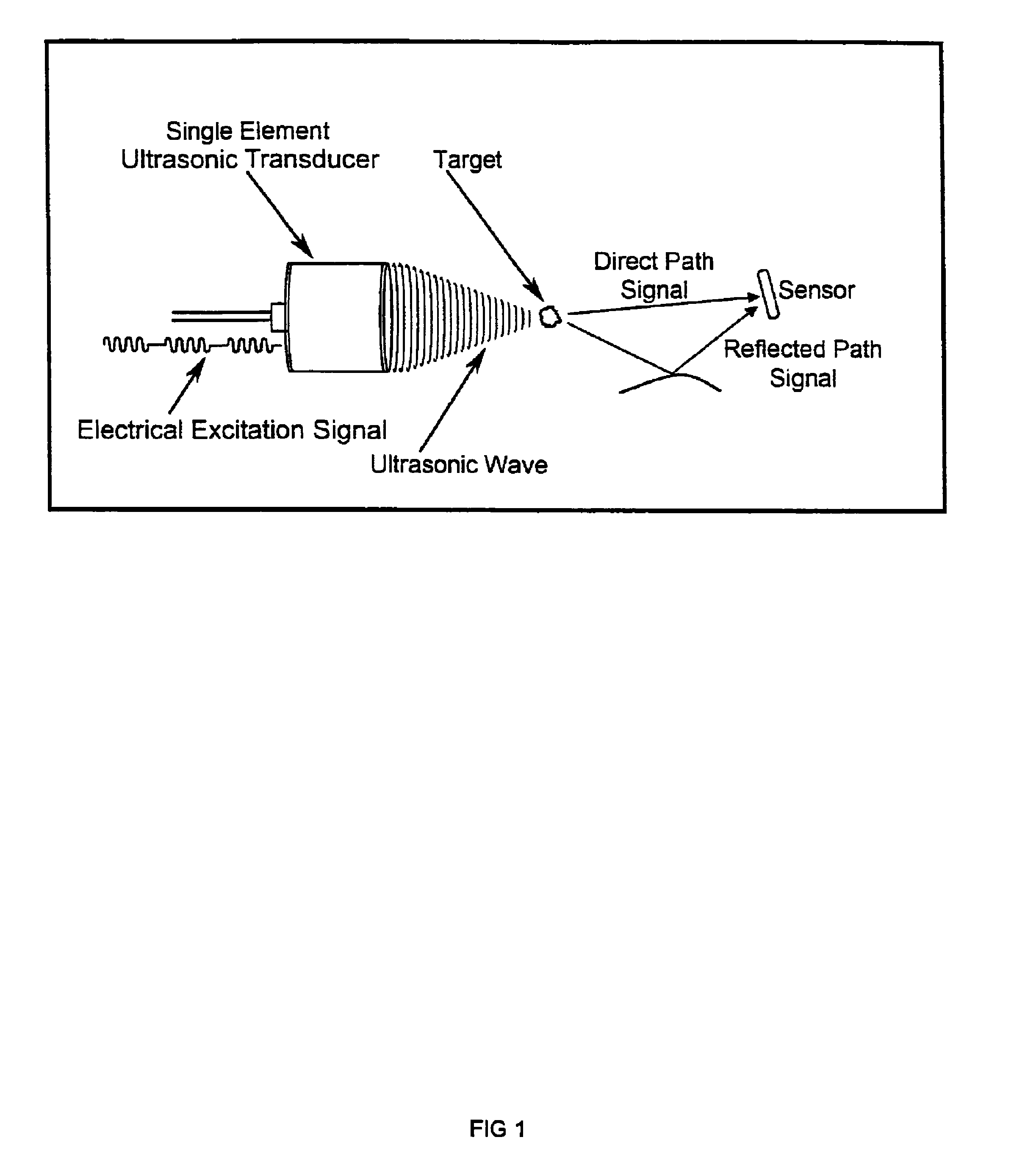
[0021]In addition to facilitating the task of locating a sound source, this invention also provides a means to dynamically determine or verify the location of the associated sensors (if they are also capable of acting as sound sources) which permits the use of a flexible array matrix. A flexible array matrix facilitates adaptability to different physical situations and makes it easier to maintain acoustic coupling with the body.
[0022]This invention describes a transmission method in which a modulation envelope is applied to an ultrasound signal. In addition to facilitating the task of locating a sound source, the modulation envelopes described herein have advantages over other envelopes in terms of enhancing the ability to detect or receive the signals emanating from a sound source in the presence of noise or clutter signals.
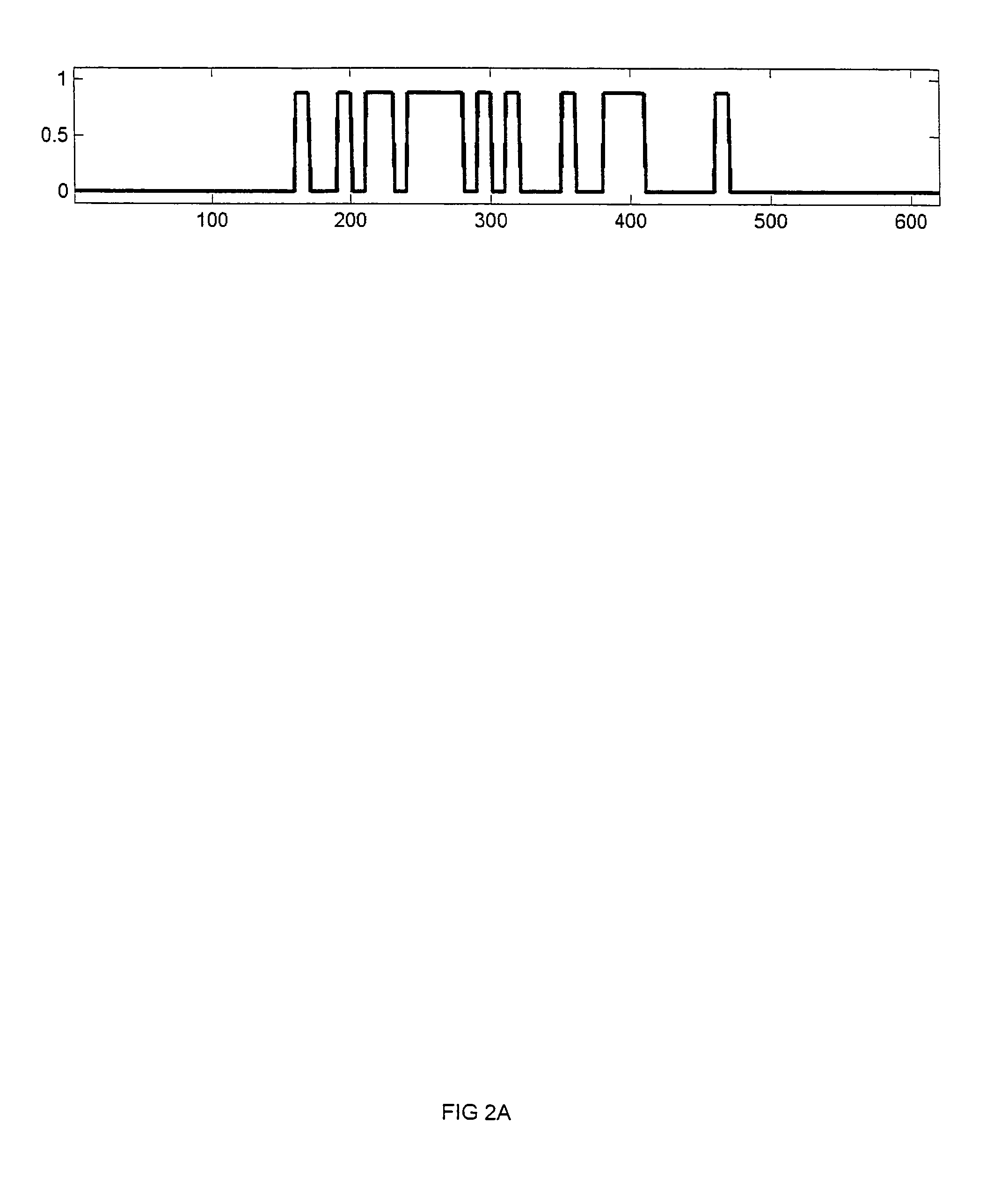
[0034]The modulation envelope of the generated ultrasound signal is selected from the group consisting of a chirp, based on a pseudorandom sequence, based on a maximum length sequence, based on a Gold sequence, and is intended to improve reception of the desired signal in the presence of multipath or clutter signals.
[0048]The modulation envelope of the generated beams of ultrasonic wave energy is selected from the group consisting of a chirp, based on a pseudorandom sequence, based on a maximum length sequence, based on a Gold sequence, and is intended to improve reception of the desired signal in the presence of multipath or clutter signals.
[0064]The modulation envelope of the generated at least one beam of ultrasonic wave energy is selected from the group consisting of a chirp, based on a pseudorandom sequence, based on a maximum length sequence, based on a Gold sequence, and is intended to improve reception of the desired signal in the presence of multipath or clutter signals.

Problems solved by technology

Unfortunately, mammograms have a number of drawbacks.
Fibroglandular tissue, which is normal in breasts, also appears as white which leads to poor contrast in mammographic images.
Second, X-ray mammography is an extremely uncomfortable procedure.
Third, mammography is an x-ray based modality which involves exposure to harmful ionizing radiation.
However, MRI may be prohibitively expensive and out of reach for all but a limited number of patients with certain socioeconomic standing.
Moreover, in cases with dense breasts, mammograms have proven to have limited utility and therefore, ultrasound is the only method of choice, next to expensive and unaffordable MRI.
The prior art requires knowledge of the location of the receiving sensors in an array but provides no explicit method for determining the locations.
There has been extensive prior art using coded signals with sharp autocorrelation functions to determine distances in radar, sonar, wire-fault-detection, and direct ultrasound imaging, but there has been no application of coded signals to Image-based Dynamic Ultrasound Spectrography (IDUS), Acoustic Radiation Force Imaging (ARFI), or similar imaging modalities.
A rigid mechanical framework could be used to position the sensors and transducer in fixed, known locations relative to one another but this arrangement is less than ideal in terms of adaptability and the need to maintain contact with the body.

Method used


Image

  • Use of coded excitation schemes in the detection and location of a target in a human body such as breast calcifications
  • Use of coded excitation schemes in the detection and location of a target in a human body such as breast calcifications
  • Use of coded excitation schemes in the detection and location of a target in a human body such as breast calcifications

Examples


Embodiment Construction

[0086]Although specific embodiments of the present invention will now be described with reference to the drawings, it should be understood that such embodiments are by way of example only and merely illustrative of but a small number of the many possible specific embodiments which can represent applications of the principles of the present invention. Various changes and modifications obvious to one skilled in the art to which the present invention pertains are deemed to be within the spirit, scope and contemplation of the present invention as further defined in the appended claims.

[0087]The nature of the sound transmission medium, in this case human breast tissues, can vary widely. In addition, physical features of interest such as microcalcifications and tumors may be characterized by rough edges, branching structures, irregular geometries, and complex spatial distributions, and thereby may respond to a stimulating signal or multiplicity of stimulating signals and emit signal energ...


PUM


Abstract

A method for detecting a target or targets in a medium. The method incorporates generating beams of ultrasonic wave energy each having a modulation envelope and causing each beam of wave energy to impact a target region having a multiplicity of targets and demodulating each signal generated by vibration of each target caused by the interaction of a respective ultrasound wave energy beam having a modulation envelope with each of the targets and receiving each demodulated signal from each target by a multiplicity of sensors. Thereafter, each time-of-flight of each demodulated signal from each of the targets to each of the multiplicity of sensors is computed to determine the location of a respective target.

Description

BACKGROUND OF THE INVENTION[0001]1. Field of the Invention[0002]The present invention relates, in general, to the detection of targets within the human body. The present invention also relates in particular to the detection and localization of microcalcifications in the human breast which may be indicative of the presence of breast cancer.[0003]2. Description of the Prior Art[0004]Breast cancer is often characterized by the presence of calcifications along mammary ducts. These may be detected using X-ray mammography techniques. Unfortunately, mammograms have a number of drawbacks. First, calcifications appear as white / shiny dots in a generally black-and-white background. Fibroglandular tissue, which is normal in breasts, also appears as white which leads to poor contrast in mammographic images. Second, X-ray mammography is an extremely uncomfortable procedure. Third, mammography is an x-ray based modality which involves exposure to harmful ionizing radiation.[0005]An alternative app...

Claims


Application Information

Patent Timeline
Patent Type & Authority Patents(United States)
IPC IPC(8): A61B8/00A61B8/14
CPCA61B8/0825A61B8/54G01S7/52036G01S15/8959A61B8/4483
Inventor O'RUANAIDH, JOSEPHGRAFF, DAVID STEVENVECCHIO, CHRISTOPHER J.RAMBOD, EDMONDSNUKAL, ROBERT M.
Owner QUANTASON
Learn More