
Insulation displacement connector (IDC)

a technology of displacement connectors and connectors, applied in the direction of coupling device connections, coupling device details, contact members penetrating/cutting insulation/cable strands, etc., can solve the problem of limiting the number of wire connections that could otherwise be made on a smaller contact footprint or pad

Active Publication Date: 2012-02-07
KYOCERA AVX COMPONENTS CORP
View PDF16 Cites 21 Cited by
  • Summary
  • Abstract
  • Description
  • Claims
  • Application Information

AI Technical Summary

Benefits of technology

[0008]Objects and advantages of the invention will be set forth in part in the following description, or may be obvious from the description, or may be learned through practice of the invention.

Problems solved by technology

As electronic components become smaller and smaller, the space (“real estate”) on the circuit boards becomes increasingly more valuable and, in this regard, the housing members of conventional multi-wire IDC's tend to waste precious space on the boards.
In addition, the shape and configuration of the typical contact / housing component limits placement and orientation of the connector on the board, which limits the number of wire connections that could otherwise be made on a smaller contact footprint or pad.

Method used


Image

  • Insulation displacement connector (IDC)
  • Insulation displacement connector (IDC)
  • Insulation displacement connector (IDC)

Examples


Embodiment Construction

[0030]Reference will now be made to embodiments of the invention, one or more examples of which are illustrated in the figures. The embodiments are provided by way of explanation of the invention, and are not meant as a limitation of the invention. For example, features illustrated or described as part of one embodiment may be used with another embodiment to yield still a further embodiment. It is intended that the present invention encompass these and other modifications and variations as come within the scope and spirit of the invention.

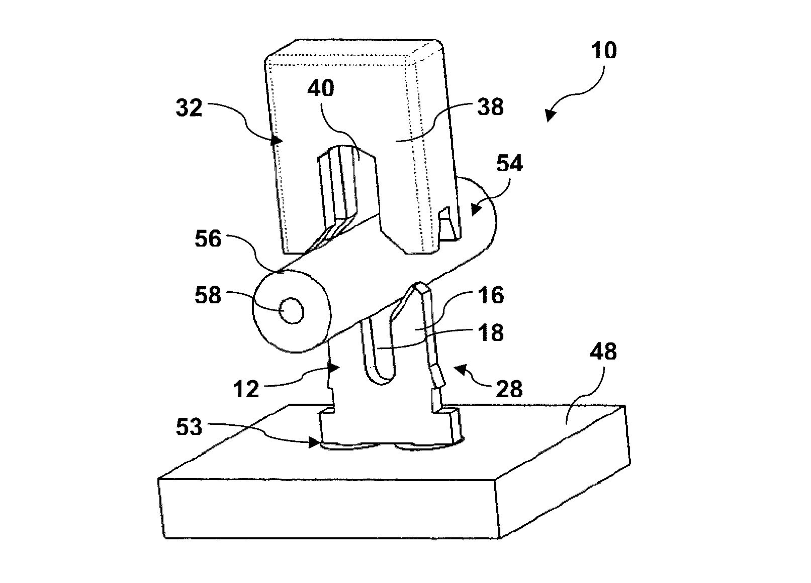
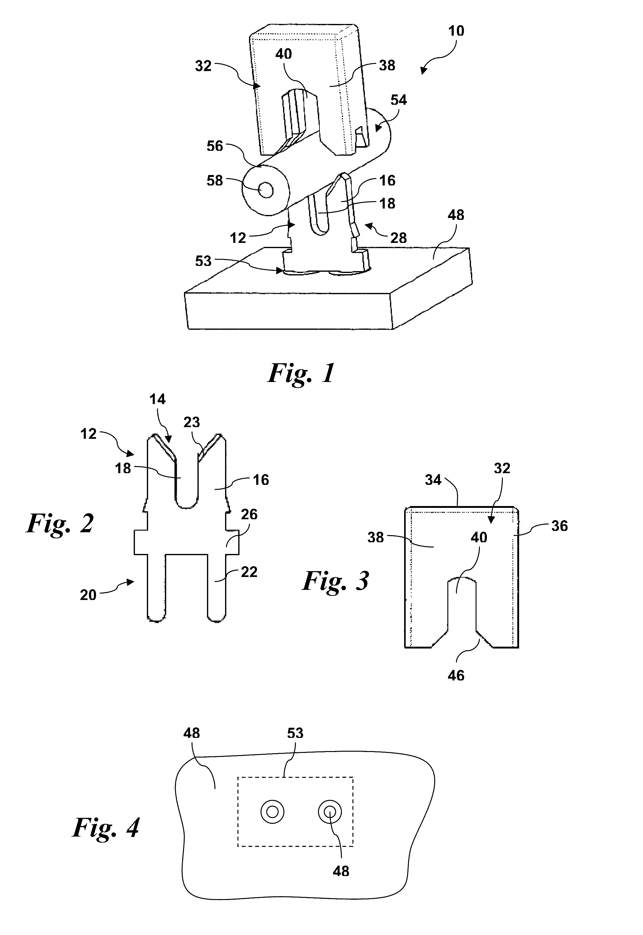
[0031]FIG. 1 is a perspective view of an embodiment of an insulation displacement connector 10 in accordance with aspects of the invention. The connector 10 is, in this particular embodiment, intended to connect a single insulated core wire 54 to a contact position 53 on a circuit board 48. The wire 54 includes an outer sheath 56 of insulation material surrounding a conductive core 58. The connector 10 makes electrical contact with the core 58 and ...


PUM


Abstract

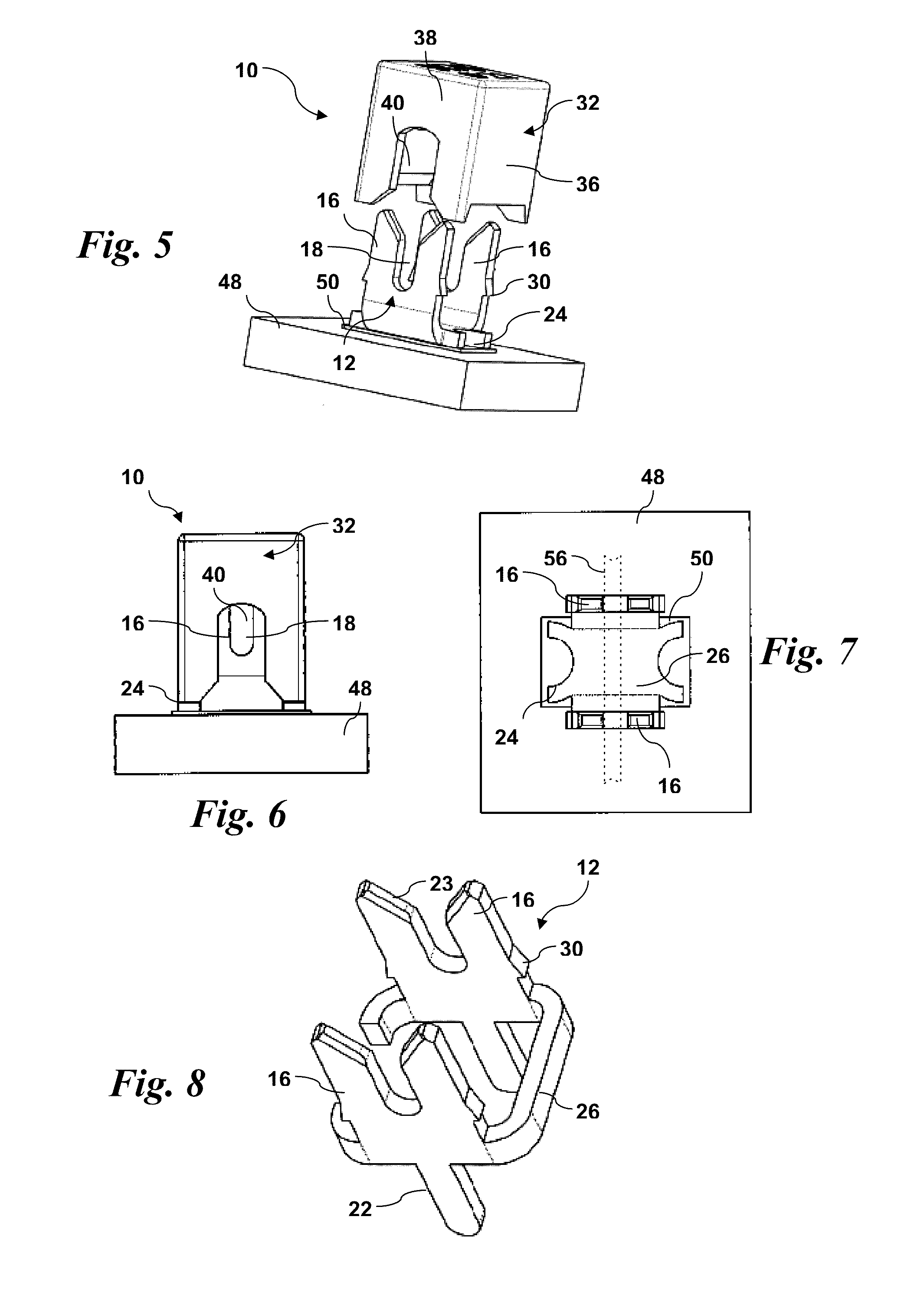
An electrical insulation displacement connector includes a bare single-wire contact element having a first end defined by opposed blades that define a receipt aperture for an insulated wire, and a second end configured for direct electrical contact at a contact position on a printed circuit board. Retaining structure is defined on the blades. A cap is configured for fitting over the exposed bare blades. The cap includes side walls and end walls with a slot defined in each of the end walls that align with the blade aperture. The side walls are engaged by the retaining structure upon pressing the cap onto the blades. The slots in the end walls of the cap have a width and height such that upon fully pressing the cap onto the blades, the slots engage and longitudinally align the insulated wire into the blade aperture so that the blades pierce and make electrical contact with a core in the insulated wire.

Description

FIELD OF THE INVENTION[0001]The present invention relates generally to the field of electrical connectors, and more particularly to insulation displacement connectors (IDC) used to connect one or more insulated wires to a component, such as a printed circuit board (PCB).BACKGROUND[0002]Insulation displacement connectors (IDC) are well known in the art for forming connections between an insulated wire and any manner of electronic component. These connectors are typically available as sockets, plugs, and shrouded headers in a vast range of sizes, pitches, and plating options. A common feature of IDC's is one or more contact elements incorporating a set of blades or jaws that cut through the insulation around the wire and make electrical contact with the conductive core in a one-step process, thus eliminating the need for wire stripping and crimping, or other wire preparation. IDC's are used extensively in the telecommunications industry, and are becoming more widely used in printed ci...

Claims


Application Information

Patent Timeline
IPC IPC(8): H01R4/24
CPCH01R12/71H01R4/2433H01R12/515H01R43/015H01R4/24H01R4/2425H01R4/2454H01R4/2404H01R13/58H01R13/5804H01R13/5808H01R13/5812H01R13/5816
Inventor BISHOP, PETERHUNTLEY, NORMAN
Owner KYOCERA AVX COMPONENTS CORP
Learn More