
Scraper device, as well as construction machine

a technology of swivelling device and construction machine, which is applied in the direction of manufacturing tools, vehicle cleaning, and cleaning, etc., can solve the problems of high surface pressure, time-consuming bolt removal, and high surface pressure, and achieve the effect of low design height, large swivelling angle and low design height of swivelling devi

Active Publication Date: 2012-01-24
WIRTGEN AMERICA
View PDF13 Cites 21 Cited by
  • Summary
  • Abstract
  • Description
  • Claims
  • Application Information

AI Technical Summary

Benefits of technology

The solution achieves a low design height, small swivelling radius, and automatic operation, enabling a swivelling angle of over 90° with reduced wear and tear, suitable for use between the front and rear axles of construction machines.

Problems solved by technology

In summary, the known state of the art has the following disadvantages:Lifting cylinders simultaneously designed for lifting as well as for swivelling have a too large design height,the swivelling radius is larger with these solutions, which requires the rear travel drive units to be arranged far towards the rear,manual removal of the bolts is time-consuming and requires effort,if one of the bolts gets jammed, it needs to be removed manually using a tool, which involves a lot of effort,the use of bolts has the disadvantage of a small contact surface, which results in a high surface pressure and high wear and tear,the achievable swivelling angle is too small,the design height of single-part scraper devices is so large that it is suitable only where the milling drum is arranged at the rear end of the construction machine, and not between the front axle and the rear axle below the machine frame.
This support also brings about an as large contact surface as possible and thus low surface pressures, which lead to low wear and tear.

Method used


Image

  • Scraper device, as well as construction machine
  • Scraper device, as well as construction machine
  • Scraper device, as well as construction machine

Examples


Embodiment Construction

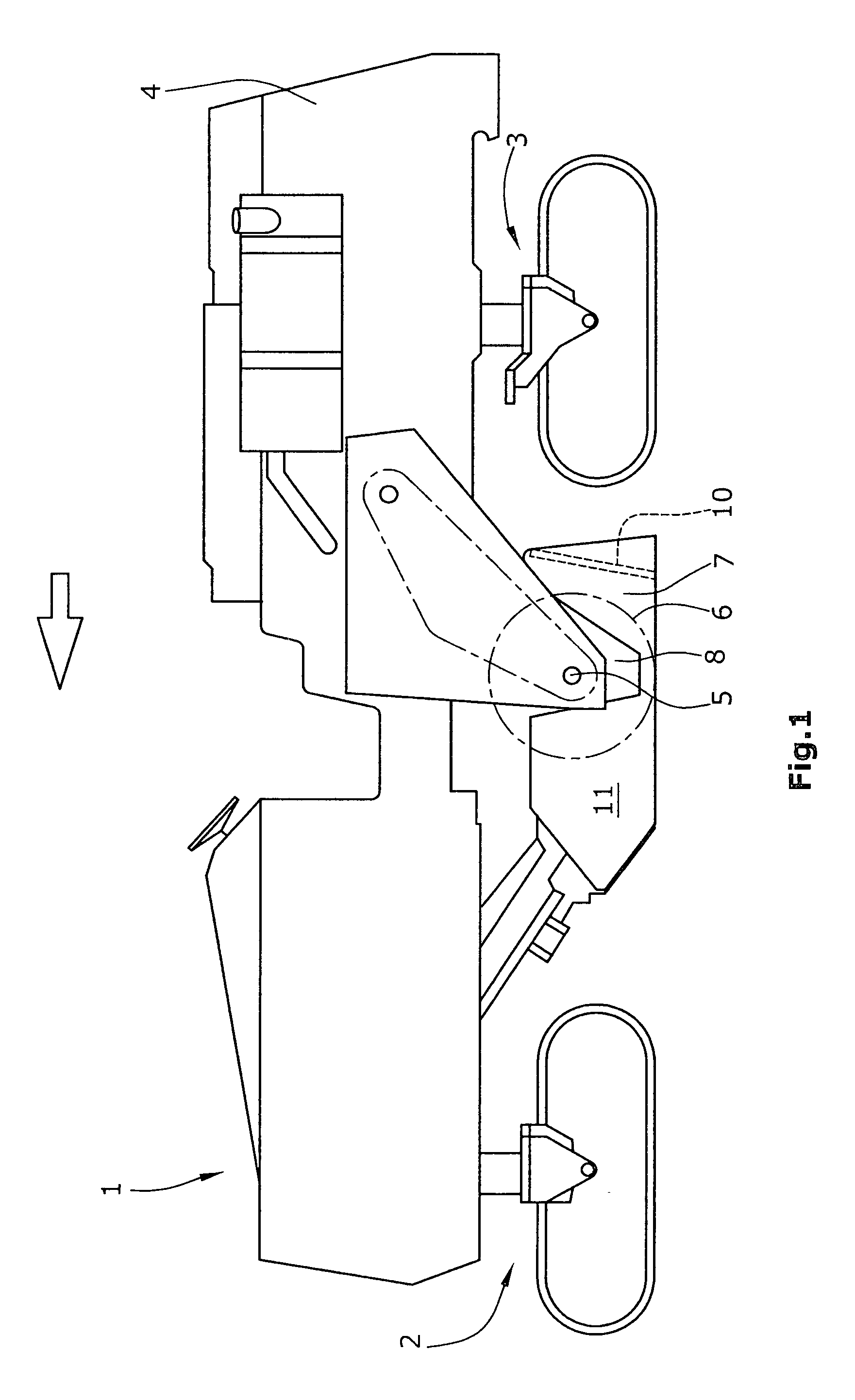
[0047]FIG. 1 shows an automotive road milling machine 1 in the design of a large milling machine, in which a milling drum 6 is mounted between front and rear travel drive units 2, 3 with a milling drum axis 5 in lateral walls 8 of the machine frame 4.

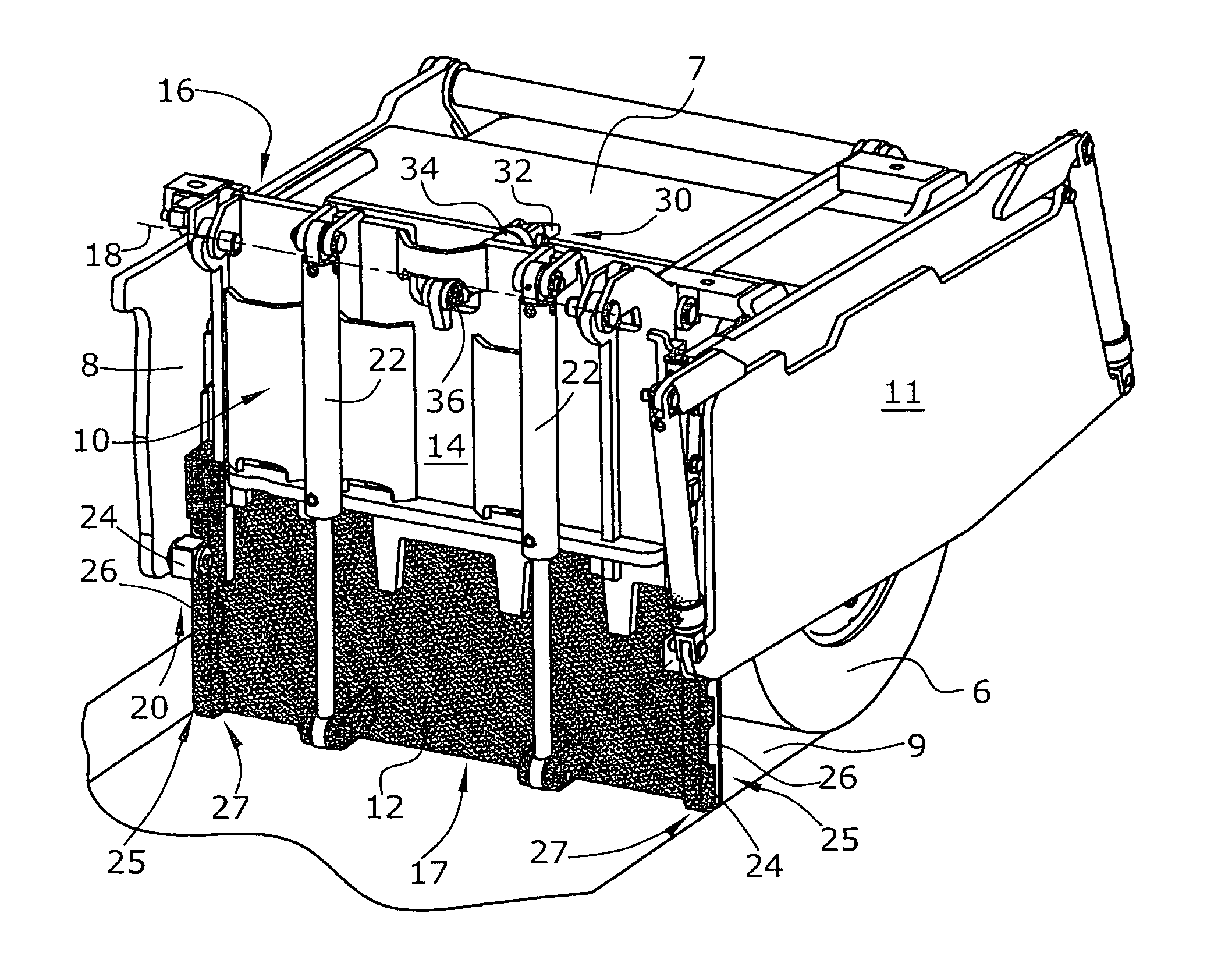
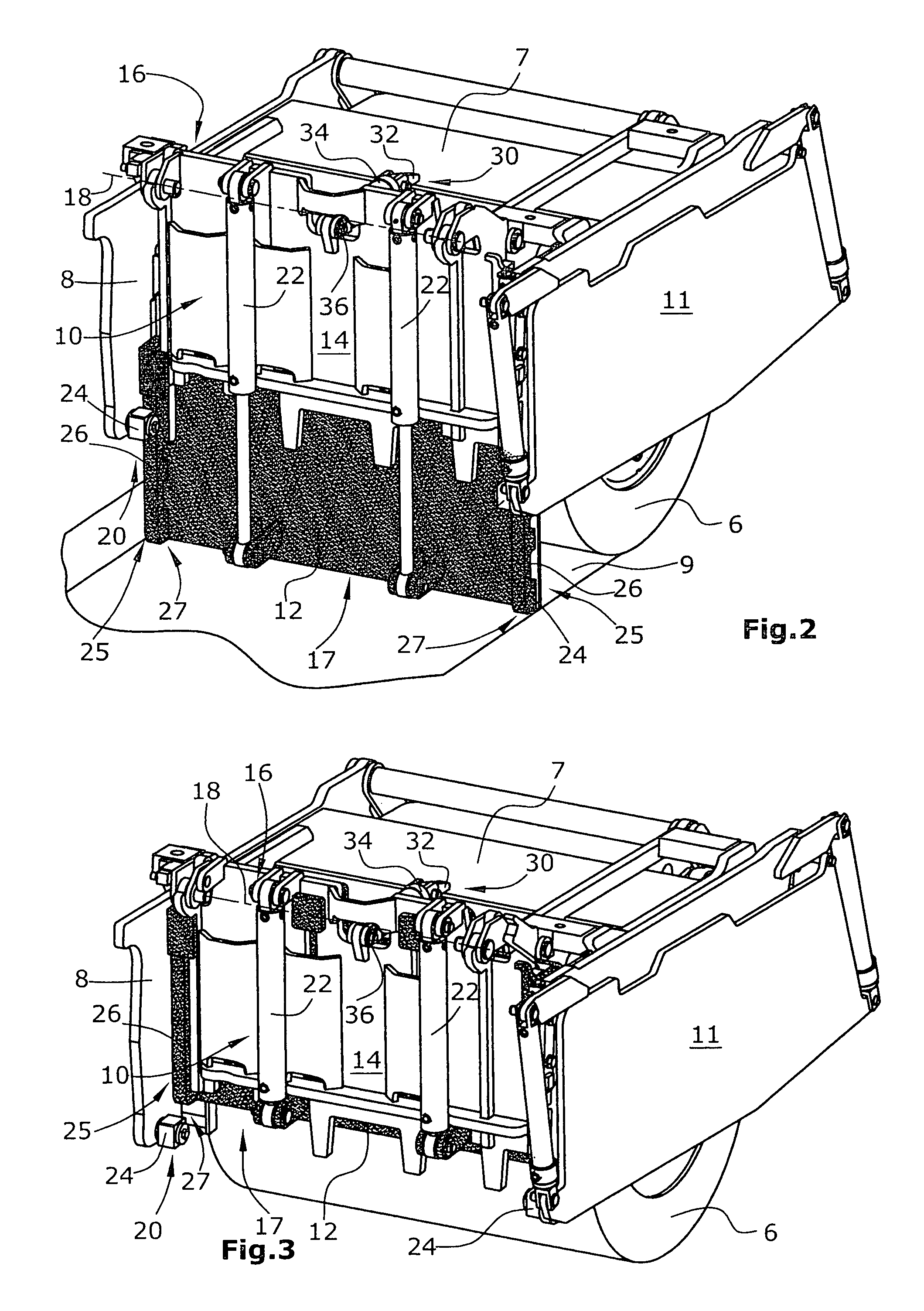
[0048]The milling drum 6 is surrounded by a drum casing 7 attached to the machine frame 4, the said drum casing 7 being provided with, at the rear end when seen in the direction of travel, a scraper device with a two-part scraper blade 10. The lower part 12 of the scraper blade 10 can glide over the ground surface 9 milled off by the milling drum 6 during operation, with the lower part 12 of the scraper blade 10 being adjustable in height relative to the milling drum 6.

[0049]It goes without saying that the scraper device with a two-part scraper blade 10 is also suitable for use in other road milling machines of different design.

[0050]In addition to the side walls 8, a height-adjustable side plate 11 may additionally be provided as edge ...


PUM

PropertyMeasurementUnit
swivelling angleaaaaaaaaaa
heightaaaaaaaaaa
swivelling radiusaaaaaaaaaa

Abstract

A scraper device for a milling drum mounted in a construction machine at a machine frame between lateral walls with a milling drum axis, with a two-part scraper blade arranged in a height-adjustable fashion behind the milling drum when seen in the direction of travel, the lower part of which can glide over the ground surface milled off by the milling drum, where the lower part of the scraper blade is adjustable in height when in operating position, it is provided that the upper part of the scraper blade is attached, at the upper end, to swivel about a swivelling axis parallel to the axis of the milling drum, that the scraper blade, when in operating position, is engaged with lateral retaining devices at the lateral walls, which retain the scraper blade in a position running essentially orthogonally to the ground surface, that a swivelling device is capable of swivelling the scraper blade about the swivelling axis when the scraper blade is disengaged from the lateral retaining devices, and that the swivelling device is provided, at the upper end of the upper part of the scraper blade, with an operating device articulated between a permanently installed part of the construction machine and the upper part of the scraper blade.

Description

BACKGROUND OF THE INVENTION[0001]The invention relates to a scraper device, as well as a construction machine.[0002]A scraper device for a milling drum mounted in a construction machine at a machine frame in lateral walls, with a scraper blade arranged in a height-adjustable fashion behind the milling drum when seen in the direction of travel, is known from DE 10 2005 058 102. With this scraper device, the lower part of the scraper blade can glide over the ground surface milled off by the milling drum, with the scraper blade being guided in a height-adjustable fashion relative to the milling drum.[0003]From DE 35 28 038, it is known in a scraper device with a single-part scraper blade to use a scraper blade capable of swivelling. A laterally arranged retaining groove causes the lifting movement of the scraper blade to turn into a swivelling movement towards the end of the path of a lifting cylinder.[0004]It is also known from U.S. Pat. No. 5,505,598 and U.S. Pat. No. 5,474,397 to us...

Claims


Application Information

Patent Timeline
Patent Type & Authority Patents(United States)
IPC IPC(8): E01C19/00
CPCE01C23/088E01C23/127E02F3/783E02F3/7645
Inventor KOTTING, HEINZLEY, HERBERTHAHN, GUNTER
Owner WIRTGEN AMERICA
Learn More