Power head movement friction pair for down-hole drilling machine

A technology of motion friction and down-the-hole drilling rigs, which is applied to the driving device for drilling in the wellbore, drilling equipment, earthwork drilling and production, etc. It can solve the problems of fast wear of the guide rail, low service life of the guide rail, and large sliding contact surface. Reduce the wear of the guide rail, prolong the service life, the effect of small contact surface and running resistance

Inactive Publication Date: 2015-03-18
HUBEI SHOUKAI MACHINERY
View PDF0 Cites 0 Cited by
  • Summary
  • Abstract
  • Description
  • Claims
  • Application Information

AI Technical Summary

Problems solved by technology

[0003] The purpose of the present invention is to solve the problems of sliding friction between the connecting plate and the guide rail of the moving friction pair of the power head of the traditional down-the-hole drilling rig, large sliding contact surface, large running resistance, fast wear speed of the guide rail and low service life of the guide rail. Provide a kind of kinematic friction pair of the power head of the down-the-hole drilling rig that can better overcome the above-mentioned defects

Method used


Image

  • Power head movement friction pair for down-hole drilling machine
  • Power head movement friction pair for down-hole drilling machine
  • Power head movement friction pair for down-hole drilling machine

Examples


Embodiment Construction

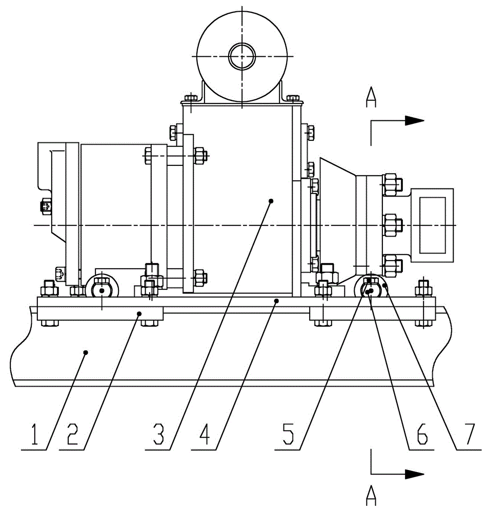
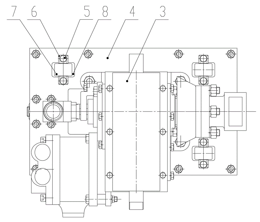
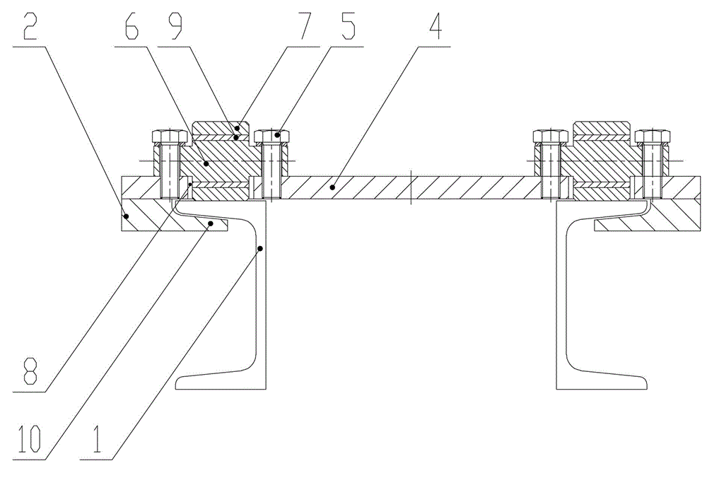
[0011] see figure 1 , figure 2 with image 3 , the present invention includes a guide rail 1, on which a power head mount is slidably installed, and the power head mount has a connecting plate 4 that is slidably mounted on the top of the guide rail 1, and the top of the connecting plate 4 is fixedly equipped with a power head 3 and a connecting plate 4 Two pairs of guide plates 2 are installed on the left and right sides of the bottom, and the bottom of each guide plate 2 is provided with a hook plate 10 protruding from the guide rail 1. The hook plate 10 buckles the guide rail 1 and cooperates with the guide rail 1; especially: Two pairs of roller mounting holes 8 are arranged on the connecting plate 4 directly above the two guide rails 1, and a rotatable roller 7 is installed in each roller mounting hole 8, and the bottom of the rollers 7 is lower than the bottom of the connecting plate 4 and connected to the bottom of the connecting plate 4. Rail 1 rolling connection.

...


PUM


Abstract

The invention discloses a power head movement friction pair for a down-hole drilling machine. The power head movement friction pair for the down-hole drilling machine comprises guide rails, wherein a power head mounting seat is mounted on the guide rails in a sliding manner and is provided with a connecting plate which is mounted at the tops of the guide rails in the sliding manner; a power head is fixedly mounted at the top of the connecting plate; a plurality of pairs of guide plates are mounted on the left side and the right side of the bottom of the connecting plate; a hook plate which extends to the guide rails is arranged at the bottom of each guide plate; the hook plates buckle the guide rails and are mounted with the guide rails in a matching manner; the power head movement friction pair for the down-hole drilling machine is characterized in that a plurality of pairs of roller mounting holes are formed in the positions, right above the two guide rails, of the connecting plate; a rotatable roller is mounted in each roller mounting hole; the bottom of each roller is lower than the bottom of the connecting plate and is in rolling connection with the guide rails. According to the power head movement friction pair for the down-hole drilling machine, the surface-surface sliding contact between the connecting plate and each guide rail is changed into the rolling contact between each roller and the guide rails, so that the contact area is small; the running resistance of the power head is reduced; the guide rails are not easily worn; the service life of the power head movement friction pair is longer.

Description

technical field [0001] The invention relates to the technical field of down-the-hole drilling machines, in particular to a moving friction pair of a power head of a down-the-hole drilling machine. Background technique [0002] At present, the kinematic friction pair of the power head of the traditional down-the-hole drilling rig includes a guide rail on which a power head mounting seat is slidably installed. The power head installation seat has a connecting plate slidably installed on the top of the guide rail, the top of the connecting plate is fixedly equipped with a power head, and the left and right sides of the bottom of the connecting plate are equipped with guide plates. The bottom of each guide plate is provided with a hook plate protruding to the guide rail, and the hook plate buckles the guide rail and cooperates with the guide rail for installation. The friction pair of the power head of this traditional down-the-hole drilling rig, because the connecting plate an...

Claims


Application Information

Patent Timeline
Patent Type & Authority Applications(China)
IPC IPC(8): E21B4/06
CPCE21B4/06
Inventor 万杏平吴少华
Owner HUBEI SHOUKAI MACHINERY
Why Eureka
Try Eureka