Device and method for at least partly dissolving a connecting layer of a temporarily bonded substrate stack

Active Publication Date: 2019-11-12
EV GRP E THALLNER GMBH
View PDF15 Cites 0 Cited by
  • Summary
  • Abstract
  • Description
  • Claims
  • Application Information

AI Technical Summary

Benefits of technology

This patent is about a method for separating a substrate stack by dissolving a portion of the connecting layer using nozzles. The nozzles are arranged in a ring-shaped pattern, which helps to dissolve the connecting layer evenly and quickly. The substrate stack remains tightly connected and can be processed without being damaged. The holding device of the substrate stack is simplified, and the device can process multiple substrate stacks at once. The entire substrate surface can be cleaned using the nozzles. The nozzle system is designed to achieve a uniform attachment and cleaning of the substrate. The number and distribution of nozzles have a significant effect on the quality and homogeneity of the cleaning. The spraying distance between the nozzle and the substrate surface should be between 0.1 to (100 mm, and the spray angle and spray width can vary depending on the type of nozzle and spraying distance.

Problems solved by technology

Detaching is increasingly turning out to be one of the most critical process steps since the thin substrates with substrate thicknesses of a few μm easily break during detachment / removal or suffer damage because of the forces that are necessary for the detaching process.
Moreover, the thin substrates have very little if any dimensional stability and typically roll without support material.

Method used


Image

  • Device and method for at least partly dissolving a connecting layer of a temporarily bonded substrate stack
  • Device and method for at least partly dissolving a connecting layer of a temporarily bonded substrate stack
  • Device and method for at least partly dissolving a connecting layer of a temporarily bonded substrate stack

Examples


first embodiment

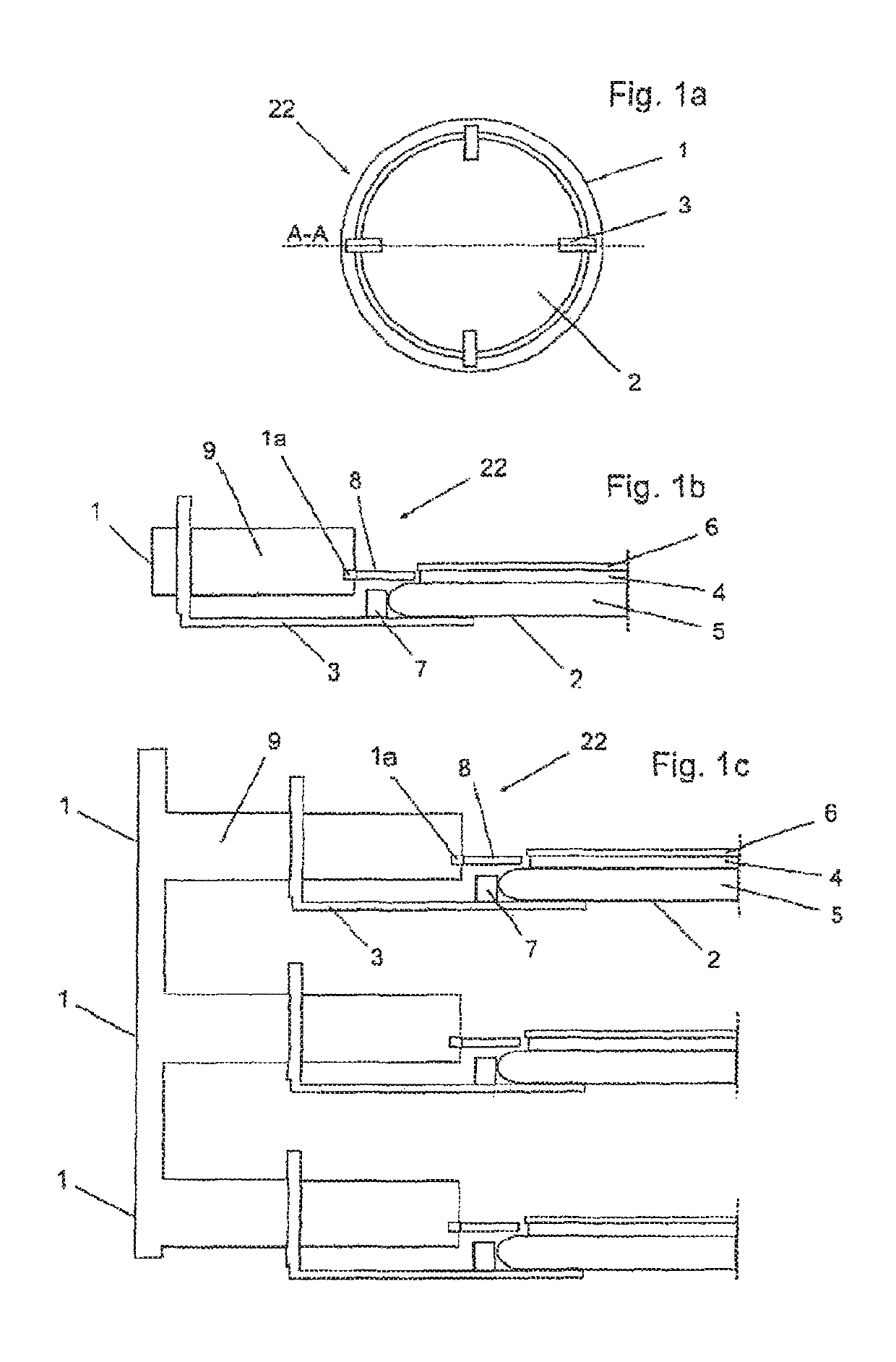
[0058]FIG. 1a diagrammatically shows a top view of a device 22 according to the invention in accordance with a first embodiment with a line of intersection A-A. FIG. 1b shows a diagrammatic half of a cross-sectional view of the device 22 along the line of intersection A-A. The other half is designed in mirror image.

[0059]As shown in the embodiment according to FIGS. 1a and 1b, the device 22 has a ring 1. The ring 1 is equipped with pivoting holding devices 3 with attaching pins 7 in order to hold a substrate stack 2 in a partial-dissolving position. The attaching pins 7 are advantageously cylindrical or have slightly conical tips, but they can also have other suitable shapes and / or sizes. The substrate stack 2 is comprised of a carrier substrate 5 and a product substrate 6, which are temporarily bonded with one another via a connecting layer e.g., an adhesive layer.

[0060]The ring 1 is mounted preferably 0.1 to 15 mm, more preferably 0.1 to 10 mm, most preferably 0.1 to 8 mm, and wit...

second embodiment

[0066]FIG. 1c shows one half of a diagrammatic cross-sectional view of a device 22 according to the invention in accordance with a The other half is designed in mirror image. In FIG. 1c, three rings 1 that are in particular designed identically as well as corresponding holding devices 3 are arranged vertically stacked one above the other. All rings 1 are installed in a closed chamber (not shown). The stacked rings 1 are connected to one another and are supplied by means of connecting lines or supply lines 9 with solvent by means of a high-power circulating pump.

[0067]Multiple rings 1 can be arranged one above the other in any number, preferably 2 to 30, more preferably 2 to 15, most preferably 2 to 10, and with utmost preference 2 to 5 rings 1, so that multiple substrate stacks 2 can be treated at the same time.

third embodiment

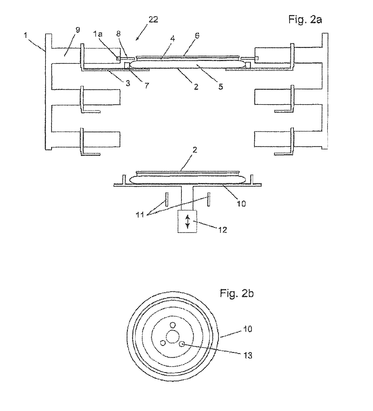
[0068]FIG. 2a diagrammatically shows a cross-sectional view of a device 22 according to the invention in accordance with a The device 22 can be designed as described in FIG. 1c, whereby the device 22 in addition has a receiving system 10. The upper ring 1 is already loaded with a substrate stack 2 in this depiction. A second substrate stack is located on the receiving system 10.

[0069]The substrate stack 2 may have been previously loaded by a robot (not shown) onto the receiving system (in particular a chuck) 10. The receiving system 10 is designed in such a way that the robot can remove the substrate stack 2 again after the loosening or partial dissolving. The substrate stack 2 is advantageously attached to the receiving system 10 that can move parallel to the z-direction (vertical direction). The receiving system 10 moves, in particular is driven over a shaft 12, upward in the z-direction and brings the substrate stack 2 into the vicinity of the middle holding device 3. After that...


PUM


Abstract

A device and method for at least partial loosening of a connecting layer of a temporarily bonded substrate stack. The device has at least one ring, whereby the substrate stack can be placed within the at least one ring, the at least one ring having a plurality of nozzles. The nozzles are arranged distributed at least over a portion of the periphery of the at least one ring, the nozzles directed onto the connecting layer. The device sprays solvent from the nozzles onto an edge area of the connecting layer.

Description

FIELD OF THE INVENTION[0001]The present invention relates generally to a device and method for at least partial loosening of a connecting layer of a temporarily bonded substrate stack.BACKGROUND OF THE INVENTION[0002]The back-thinning of product substrates in the semiconductor industry is often necessary and can be carried out mechanically and / or chemically. For back-thinning, the product substrates are in general temporarily attached to a carrier.[0003]Various methods for dissolving or destroying the connecting layer are known, such as, for example, the use of UV light, laser beams or action of temperature. Other approaches pursued separation by solvent.[0004]Detaching is increasingly turning out to be one of the most critical process steps since the thin substrates with substrate thicknesses of a few μm easily break during detachment / removal or suffer damage because of the forces that are necessary for the detaching process.[0005]Moreover, the thin substrates have very little if a...

Claims


Application Information

Patent Timeline
IPC IPC(8): B32B43/00H01L21/683H01L21/677B26F3/00H01L21/67B05B1/20
CPCB26F3/004B32B43/006H01L21/67757H01L21/67051H01L21/67092H01L21/6836H01L2221/68327B05B1/207H01L2221/68381Y10T156/1111Y10S156/941Y10T156/1933Y10S156/93
Inventor FEHKUHRER, ANDREAS
Owner EV GRP E THALLNER GMBH
Why Eureka
Try Eureka