Fuel pump layout structure in motorcycle

a technology for fuel pumps and motorcycles, which is applied in the direction of machines/engines, foldable cycles, cycle equipment, etc., can solve the problems of difficult to ensure the space of a fuel pump within a main frame, and not good for the fuel pump to project sideways, so as to prevent the fuel supply line from becoming too large, improve the reliability of the fuel pump operation, and effectively utilize the space around the frame

Active Publication Date: 2012-01-24
HONDA MOTOR CO LTD
View PDF10 Cites 5 Cited by
  • Summary
  • Abstract
  • Description
  • Claims
  • Application Information

AI Technical Summary

Benefits of technology

[0015]Further, since intake and exhaust parts connected to the engine are disposed on the other side of the rear suspension damper, the fuel pump and the intake and exhaust parts can be disposed in an optimum layout near the frame. As a result, it is possible to prevent a fuel supply line from becoming too long while positioning the fuel pump behind the engine by effectively utilizing the space around the frame.
[0016]Additionally, since the fuel pump is attached to the frame through a bracket and a rubber member is interposed between the bracket and the fuel pump and also between the bracket and the frame, vibration on the vehicle body side can be absorbed by the rubber member. As a result, vibration is no longer propagated to the fuel pump and it is possible to improve the reliability of the fuel pump operation.

Problems solved by technology

However, in the case where an auxiliary device (e.g., a starting motor) of the engine is disposed on an engine crank case, it is difficult to ensure space for a fuel pump within a main frame.
However, from the standpoint of rider's operation, it is not good for the fuel pump to project sideways.

Method used


Image

  • Fuel pump layout structure in motorcycle
  • Fuel pump layout structure in motorcycle
  • Fuel pump layout structure in motorcycle

Examples


Embodiment Construction

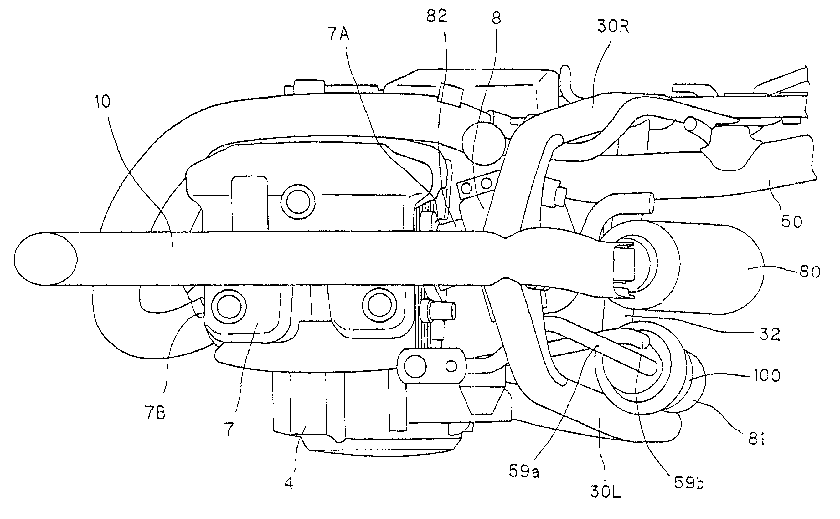
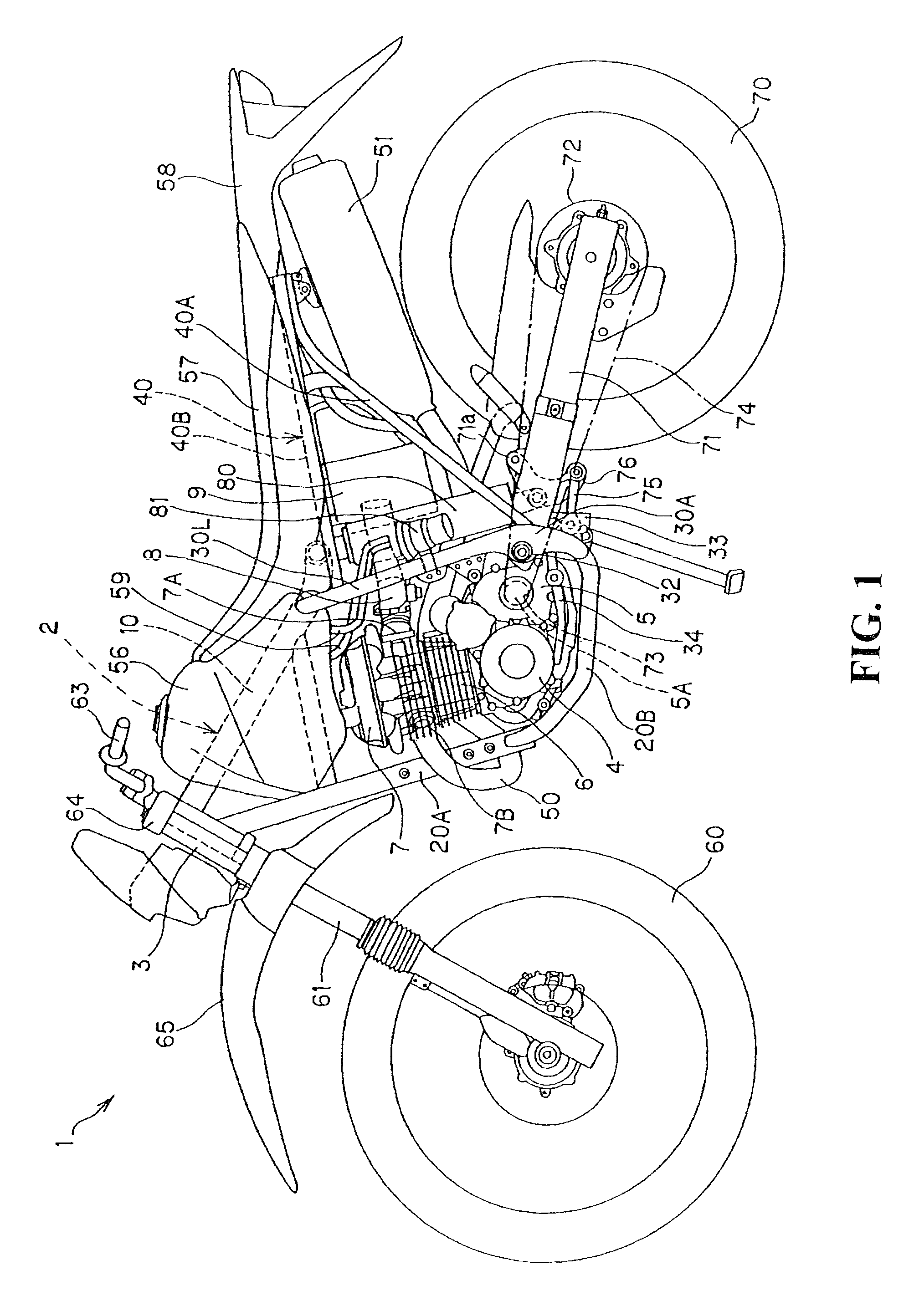
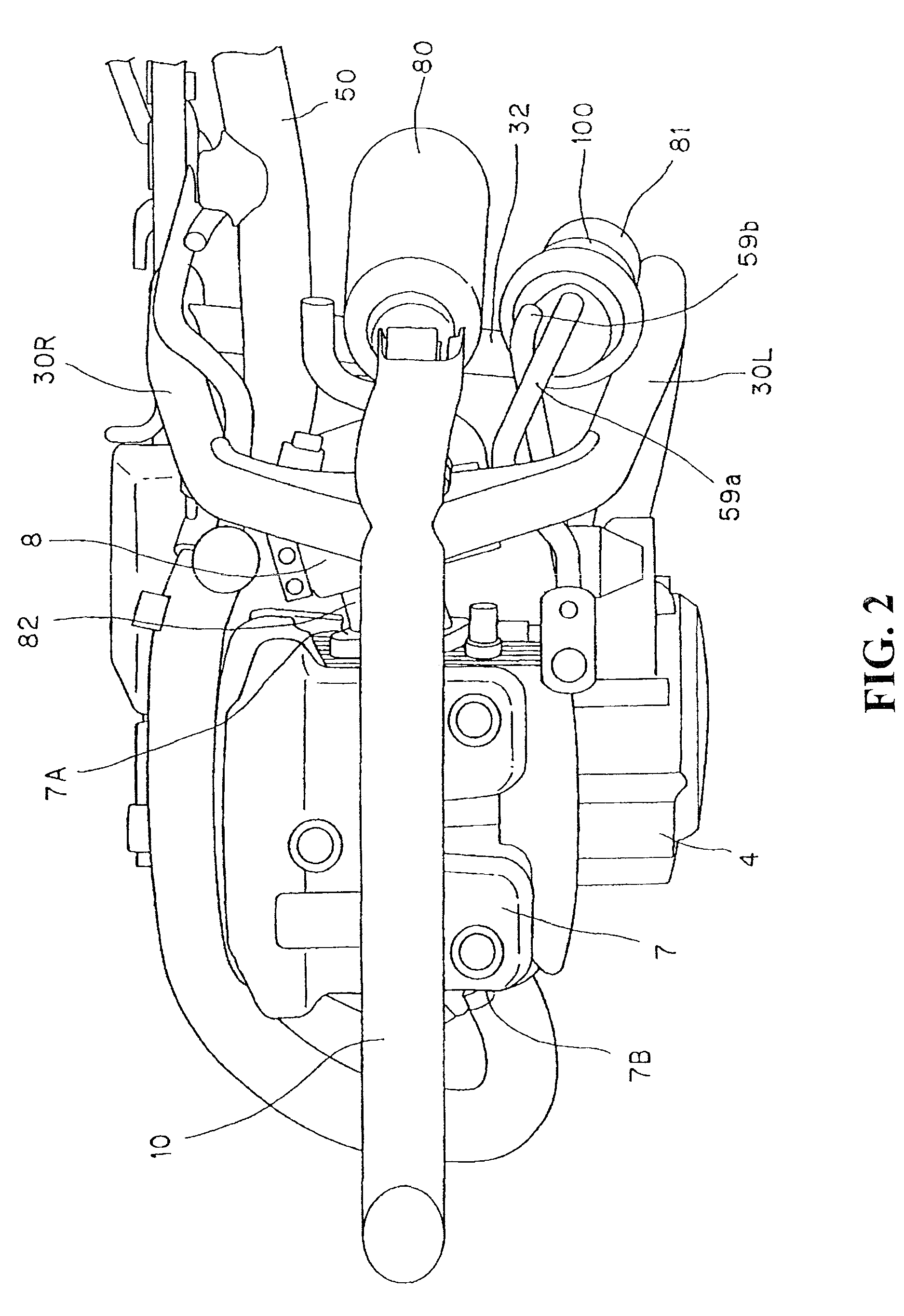
[0023]A fuel pump layout structure in a motorcycle embodying the present invention will be described with reference to the drawings. FIG. 1 is a left side view showing an off-road motorcycle 1 related to this embodiment. Directions which will be referred to in the following description are based on FIG. 1. It is assumed that a vertical direction of the vehicle body is the vertical direction in FIG. 1, a transverse direction of the vehicle body is the depth direction of the paper in FIG. 1, and a longitudinal direction of the vehicle body is the transverse direction of the paper in FIG. 1. In FIG. 1, for ease of explanation, a side cover and a shroud, which cover an outside portion of the vehicle body, are omitted.

[0024]As shown in FIG. 1, a body frame 2 of the motorcycle 1 includes a main frame 10 extending backward and obliquely downward of the vehicle body from a head pipe 3, a down tube 20A extending below the main frame 10 downwards of the vehicle body from the head pipe, a pair...


PUM


Abstract

A fuel pump layout structure in a motorcycle, including an engine, a fuel pump for the supplying fuel to the engine, a frame for supporting the engine and the fuel pump, and a rear suspension damper disposed behind the frame with a swing arm being swingably suspended from the rear suspension damper, wherein said fuel pump is disposed on one side of said rear suspension damper.

Description

BACKGROUND OF THE INVENTION[0001]The present invention relates to a fuel pump layout structure in a motorcycle for disposing a fuel pump behind an engine.[0002]There is known a motorcycle which positions a fuel pump outside a fuel tank. In a certain motorcycle of such a type, a fuel pump is disposed within a main frame (body frame) which supports an engine and behind the engine (see, for example, Japanese Patent Laid-Open No. 2005-096504).[0003]However, in the case where an auxiliary device (e.g., a starting motor) of the engine is disposed on an engine crank case, it is difficult to ensure space for a fuel pump within a main frame.[0004]According to another layout, a fuel pump is disposed sideways of the portion between an engine and a center frame which constitutes a rear portion of a main frame. However, from the standpoint of rider's operation, it is not good for the fuel pump to project sideways.SUMMARY OF THE INVENTION[0005]The present invention has been accomplished in view o...

Claims


Application Information

Patent Timeline
Patent Type & Authority Patents(United States)
IPC IPC(8): F02M37/04B62K19/30B62K19/40B62J37/00B62J99/00B62M7/02
CPCB62J37/00F02M37/04F02M37/106F02M2037/228F02M37/50
Inventor SUGIYAMA, EIJI
Owner HONDA MOTOR CO LTD
Why Eureka
Try Eureka