
System and method for emissions suppression in a switched-mode power supply

a power supply and switching-mode technology, applied in the direction of electric variable regulation, process and machine control, instruments, etc., can solve the problems of increased emi, electromagnetic interference (emi), and inability to achieve adequate shielding

Active Publication Date: 2012-01-17
INFINEON TECH AG
View PDF6 Cites 71 Cited by
  • Summary
  • Abstract
  • Description
  • Claims
  • Application Information

AI Technical Summary

Benefits of technology

The present invention relates to a method and circuit for controlling a switched-mode power supply. The technical effects of the invention include improving the efficiency and accuracy of power conversion, reducing the size and cost of power supply components, and improving the stability and reliability of power supply systems. These technical effects are achieved by a method that involves deactivating the drive signal and comparing the power supply signal to a threshold after deactivating the drive signal, and then activating the drive signal after a variable delay period has passed. This allows for a more precise and accurate response to changes in the power supply system, resulting in improved efficiency and accuracy of power conversion.

Problems solved by technology

One barrier to more efficient and cost effective switched-mode power supplies has been electromagnetic interference (EMI).
With the demand for light weight and inexpensive consumer electronics, adequate shielding is not always technically feasible or cost effective given a particular form factor and / or specification.
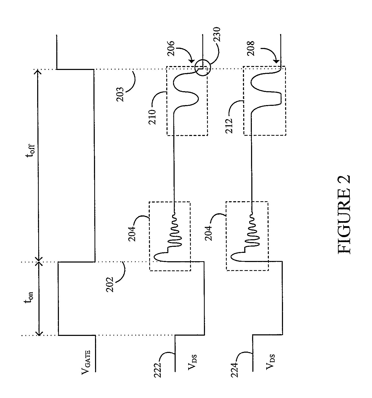
In high input voltage (e.g. Vin=230 Vac) power supply systems, however, the minimum voltage across the switch may still be appreciable during normal operation, which leads to increased EMI.

Method used


Image

  • System and method for emissions suppression in a switched-mode power supply
  • System and method for emissions suppression in a switched-mode power supply
  • System and method for emissions suppression in a switched-mode power supply

Examples


Embodiment Construction

[0020]The making and using of embodiments are discussed in detail below. It should be appreciated, however, that the present invention provides many applicable inventive concepts that may be embodied in a wide variety of specific contexts. The specific embodiments discussed are merely illustrative of specific ways to make and use the invention, and do not limit the scope of the invention.

[0021]The present invention will be described with respect to embodiments in a specific context, namely reducing EMI in a switched-mode power supply. Embodiments of this invention may also be applied to other circuits and systems that potentially emit EMI.

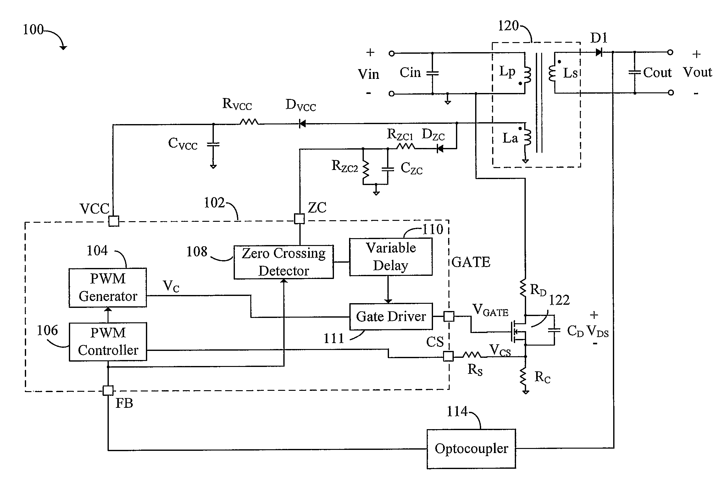
[0022]Switched-mode power supply 100 according to an embodiment of the present invention is illustrated in FIG. 1. Power supply 100 has power supply integrated circuit (IC) 102 containing pulse width modulation (PWM) generator 104, PWM controller 106, zero crossing detector 108 and variable delay 110 and gate driver 111. PWM controller 106 controls...


PUM


Abstract

In one embodiment, a method of operating a switched-mode power supply that has a switch coupled to a drive signal is disclosed. The method includes deactivating the drive signal at a first instance of time, and comparing a power supply signal to a threshold after deactivating the drive signal. The method further includes activating the drive signal a variable period of time after the power supply signal crosses the threshold.

Description

TECHNICAL FIELD[0001]This invention relates generally to power supply circuits, and more particularly to a system and method for reducing emissions in a switched-mode power supply.BACKGROUND[0002]Switched-mode power supplies are pervasive in the electronics field because of their ability to efficiently convert a first DC or AC voltage to a second regulated output level. Such power supplies are used, for example, in computer power supplies, DC power adapters, and automotive power supplies. As the demand for low power, low cost electronics have increased, however, a corresponding need for lower cost switched-mode power supplies have resulted.[0003]One barrier to more efficient and cost effective switched-mode power supplies has been electromagnetic interference (EMI). High current switching in the tens to hundreds of KHz in a typical switched-mode-power supply has the propensity to create radio-frequency emissions that interfere with communication systems. In consumer and commercial e...

Claims


Application Information

Patent Timeline
Patent Type & Authority Patents(United States)
IPC IPC(8): H02M3/335
CPCH02M1/44H02M3/33507
Inventor MAO, MING PINGTEO, YONG SIANGKOK, SIU KAM ERIC
Owner INFINEON TECH AG
Learn More