
Method and apparatus for purifying water

a technology of purification method and water purification apparatus, which is applied in the direction of vacuum distillation separation, multi-stage water/sewage treatment, separation process, etc., can solve the problems of highway traffic congestion, production water recovered from a well cannot be reused, and other related problems, so as to increase the throughput of the system, improve the efficiency of the system, and easily satisfy the demand for water purification

Active Publication Date: 2012-01-17
SHERRY RAYMOND C
View PDF42 Cites 53 Cited by
  • Summary
  • Abstract
  • Description
  • Claims
  • Application Information

AI Technical Summary

Benefits of technology

"The invention is a purification system that can clean water with many contaminants. It uses thermal energy to heat the water and reuses the energy to preheat the water and optimize the system's efficiency. The system also uses a natural gas engine to pressurize the purified water. The components of the system are modularized, so the system can be easily expanded or adjusted to meet different water purification demands. The system first removes gas and oil from the water by heating it and using a swirling vortex to separate the liquids. The purification system can be used for purifying contaminated liquid by heating it and separating the vapors from the liquid using a vortex."

Problems solved by technology

Often this is required because the impurities are toxic and otherwise not suitable for ordinary disposal, but require special treatment and handling.
The production water recovered from a well cannot be reused for the production of gas or oil from another well.
The heavy truck traffic not only places a burden on the roads, which are often rural roads, but also causes highway traffic congestion and other related problems.
It can be appreciated that this process is inefficient, costly and environmentally unsafe.
While this type of filter functions well for its intended purpose, it is adequate for water that is only mildly impure, and is not well adapted for processing huge amounts of water.
The inadequacy of a carbon filter is that such a purification process does not remove metals, bacteria and dissolved minerals.
However, the reverse osmosis membranes are generally unable to remove all inorganic and organic contaminants.
In addition, commercial reverse osmosis systems are costly as they tend to be large and require complex subsystems.
In addition, since the production water is produced with a gradually declining volume during production, it is not economical or cost effective to employ a high capacity processing system that meets the initial production water capacity, but is thereafter underutilized.

Method used


Image

  • Method and apparatus for purifying water
  • Method and apparatus for purifying water
  • Method and apparatus for purifying water

Examples


Embodiment Construction

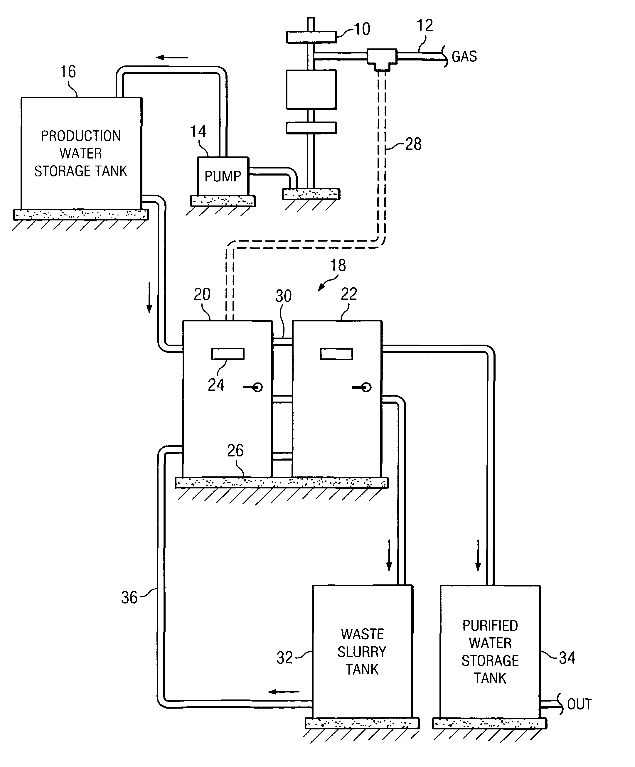
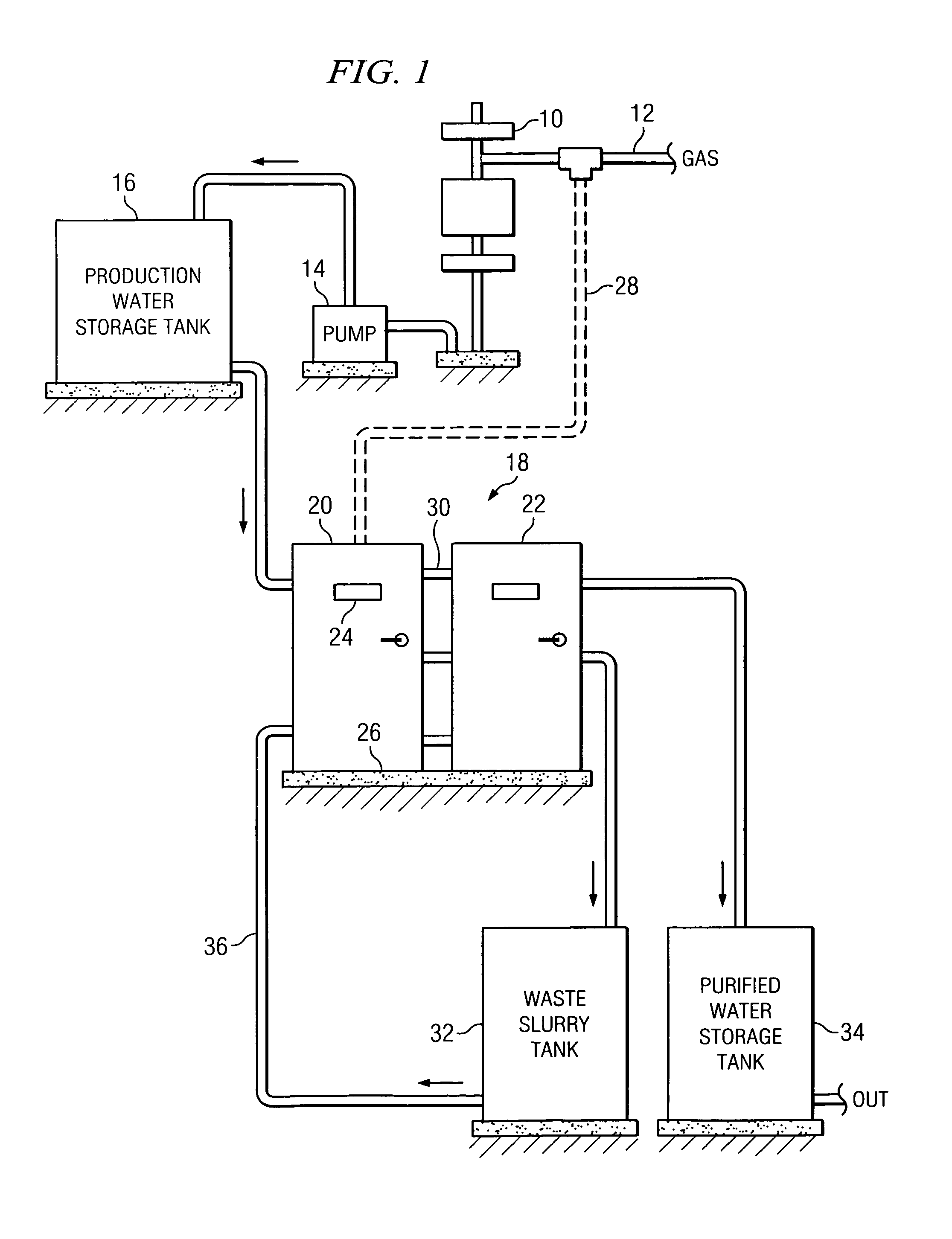
[0031]With reference to FIG. 1, there is shown an environment in which the principles and concepts of the invention can be advantageously practiced. Shown is a wellhead 10 for a gas well. The gas well produces natural gas at an outlet 12. The conventional equipment, including regulators and pumps for transporting the natural gas are not shown. In addition to the production of natural gas, the gas well also produces a large amount of production water which includes many contaminants, some of which are toxic. Some of the contaminants in the production water may include oil, salts, minerals, heavy metals, etc.

[0032]Production water is extracted from the gas well and is often naturally pressurized. In other cases the production water can be pumped with a pump 14 to a large storage tank 16. Since gas wells can initially produce 30-40 gallons of water per minute, the storage tank 16 can have a capacity of about 1,500 gallons. Typically, production water is transported by a large tank truc...


PUM

PropertyMeasurementUnit
diameteraaaaaaaaaa
diameteraaaaaaaaaa
pressureaaaaaaaaaa

Abstract

An efficient flash evaporation water purification system located at a hydrocarbon well site. An internal combustion engine uses hydrocarbon fuel from the well and drives a pump to pressurize production water from the well. The engine also generates thermal energy used to preheat the production water. An electrical generator is also driven by the engine to produce electrical power for the water purification system, as well as produce AC power for off-site consumers.

Description

RELATED APPLICATIONS[0001]This non-provisional patent application claims the benefit of provisional patent application Ser. No. 60 / 932,752 filed Jun. 1, 2007. This patent application is also related to non-provisional patent application Ser. No. 12 / 156,216 filed May 31, 2008, which issued as U.S. Pat. No. 7,693,459 B1 to Raymond C. Sherry, and is entitled “Self-Cleaning High Pressure Nozzle.”TECHNICAL FIELD OF THE INVENTION[0002]The present invention relates in general to water purification techniques, and more particularly to methods and apparatus for purifying production water produced as a byproduct from oil and gas wells.BACKGROUND OF THE INVENTION[0003]The purification of liquids is often required for various reasons. Processes are available for removing impurities from liquids to separate the same in order to properly dispose of the impurities and utilize the pure liquid. Often this is required because the impurities are toxic and otherwise not suitable for ordinary disposal, ...

Claims


Application Information

Patent Timeline
Patent Type & Authority Patents(United States)
IPC IPC(8): B01D19/00B05B17/04B05B17/00
CPCB05B1/308C02F1/06B05B15/0241B05B1/3006C02F2101/32B05B15/525
Inventor SHERRY, RAYMOND C.
Owner SHERRY RAYMOND C
Learn More