
Nail clipper

a nail clipper and nail technology, applied in the field of nail clippers, can solve the problems of affecting the cutting effect of clothing or handbags, affecting the cutting effect, and affecting the use of users, and achieve the effects of reducing production costs, convenient storage, and small siz

Inactive Publication Date: 2012-01-17
WONG WAI YIP
View PDF9 Cites 5 Cited by
  • Summary
  • Abstract
  • Description
  • Claims
  • Application Information

AI Technical Summary

Benefits of technology

[0007]In view of the aforesaid disadvantages, the object of the present invention is to provide a nail clipper which has the advantages of being safe and reliable, small in size, convenient for storage, and capable of reducing the production costs.

Problems solved by technology

Most nail clippers available on the market have open cutting edges when they are stored, thereby not only easily cutting clothing articles or handbags, but also possibly scratching users' bodies.
It is therefore very dangerous.
Besides, cutting edges will also turn blunt through constant grinding against outside objects.
Dirt is also easily accumulated in the gaps between the cutting edges.
It is inconvenient to be stored, and it is also difficult to combine it with other tools to form a multipurpose tool.
The scope of applications is therefore restricted.
Although this can prevent the cutting edges of the nail clipper from cutting the clothing articles or the bodies when it is stored and can protect the cutting edges, the casing is easily lost and the user needs to open the casing to take out the nail clipper before use and then to adjust the press lever of the nail clipper for use and it is therefore inconvenient.
While the cutting edges come into abutting contact, nevertheless the left and right ends thereof are generally projecting corners and do not form a smooth surface, and so there are still the risks of scratching users' bodies.
Further, gaps also exist between the cutting edges and they easily hold dirt, thereby affecting hygiene.
Although this proposal can resolve the problem of having the cutting edges exposed when the nail clipper is stored, the sleeve has to be produced with additional materials, thereby increasing the production costs.
However, as the protruding fastener abrades against the receiving fastener over a long period of time, the protruding fastener is easily worn out and broken and the nail clipper fails to attain the effects of being convenient and durable.

Method used


Image

  • Nail clipper
  • Nail clipper
  • Nail clipper

Examples


Embodiment Construction

[0031]The preferred embodiment of the present invention is further described in detail with the following embodiment and the accompanying drawings.

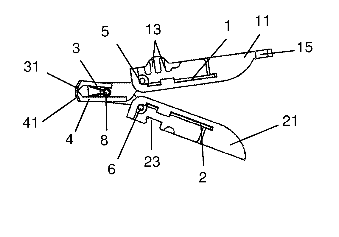
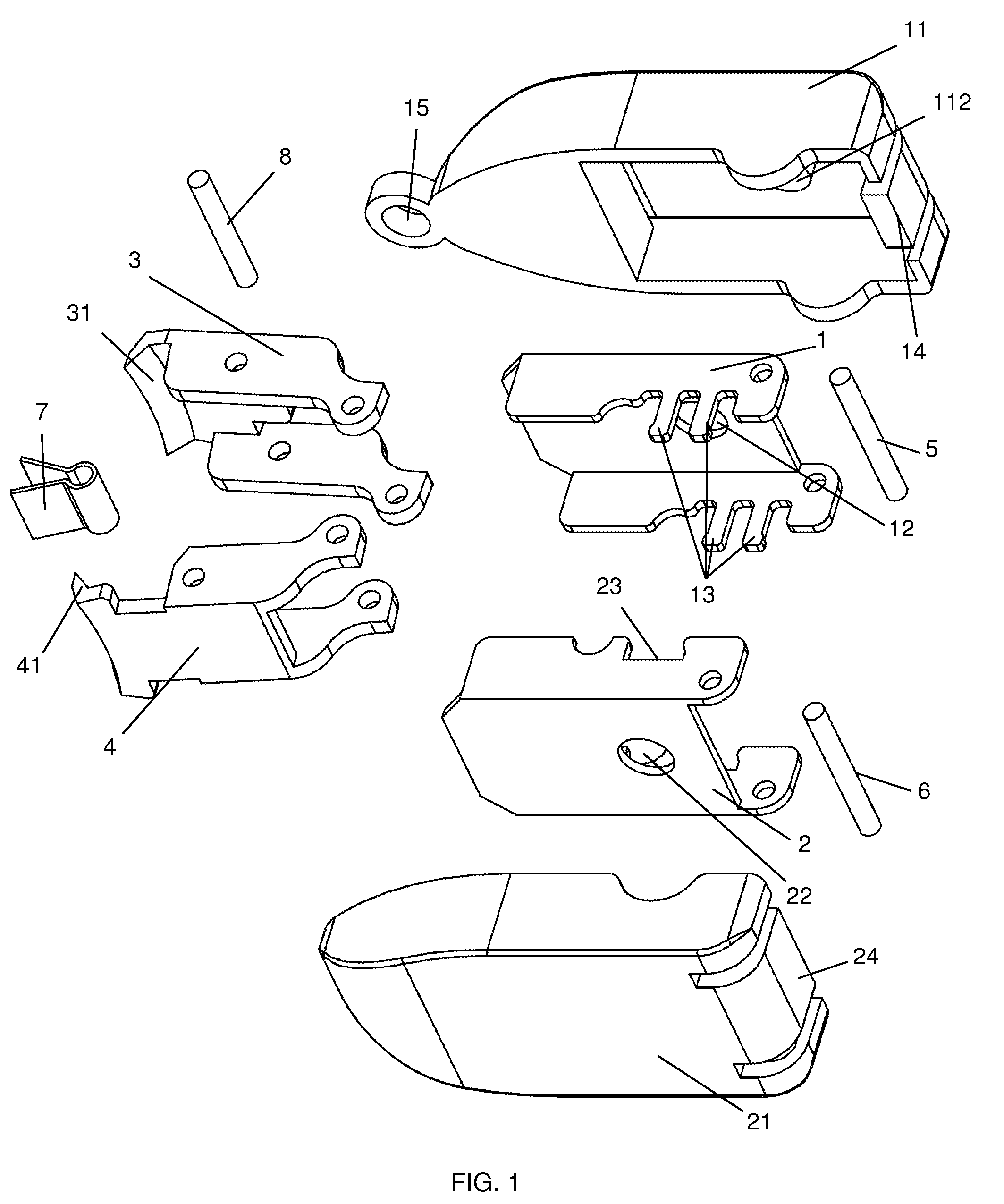
[0032]As illustrated in FIGS. 1 and 2, a nail clipper comprising a slender body formed by an upper press lever 1 and a lower press lever 2 which are movably engaged, an upper cover 11 and a lower cover 21 which are fitted onto the outer surfaces of the upper press lever 1 and the lower press lever 2 respectively to form a slender etui. In the present embodiment, the lengths of the upper cover 11 and the lower cover 21 are slightly longer than the lengths of the upper press lever 1 and the lower press lever 2, the widths of the upper cover 11 and the lower cover 21 are slightly longer than the widths of the upper press lever 1 and the lower press lever 2, the heights of the two sides of the upper cover 11 and the lower cover 21 are slightly higher than the heights of the two sides of the upper press lever 1 and the lower press lever 2, the...


PUM


Abstract

The present invention is a nail clipper. It has a slender body formed by an upper press lever and a lower press lever which are movably engaged, an upper cover and a lower cover which are respectively fitted onto the outer surfaces of the upper press lever and the lower press lever to form a slender etui, a lower blade which is movably pivotally engaged with one end of the upper press lever by means of a first pivotal axle, and an upper blade which is movably pivotally engaged with one end of the lower press lever by means of a second pivotal axle.

Description

BACKGROUND OF THE INVENTION[0001]The present invention relates to a nail clipper and more particularly pertains to a nail clipper capable of being folded into a portable body in the shape of an etui, and belongs in the field of manicuring and pedicuring implements.[0002]Most nail clippers available on the market have open cutting edges when they are stored, thereby not only easily cutting clothing articles or handbags, but also possibly scratching users' bodies. It is therefore very dangerous. Besides, cutting edges will also turn blunt through constant grinding against outside objects. Dirt is also easily accumulated in the gaps between the cutting edges. The lifetime of such a nail clipper is thus shortened. As the cutting edges of the nail clipper are open, its thickness is increased, and an irregular shape is exhibited. It is inconvenient to be stored, and it is also difficult to combine it with other tools to form a multipurpose tool. The scope of applications is therefore rest...

Claims


Application Information

Patent Timeline
Patent Type & Authority Patents(United States)
IPC IPC(8): A45D29/02
CPCA45D29/02
Inventor WONG, WAI YIP
Owner WONG WAI YIP
Learn More