Method for producing a thermoplastic plastic film, film and use thereof

a thermoplastic and film technology, applied in the field of polycarbonate foils, can solve the problems of affecting the surface quality of the multi-layer web, e.g. lines and streaks, and achieve the effects of improving surface quality, low thickness tolerance, and good birefringence properties

Inactive Publication Date: 2012-01-10
ROHM GMBH
View PDF32 Cites 7 Cited by
  • Summary
  • Abstract
  • Description
  • Claims
  • Application Information

AI Technical Summary

Benefits of technology

[0014]An object was to provide a foil which is composed of plastic and which firstly has extremely good birefringence properties in the region of EP 1 117 731 B1 or of EP 1 285 742 A2 and secondly again achieves improved surface quality. The foil should moreover again exhibit relatively low thickness tolerances across the entire region of the foil. The improved surface quality and thickness tolerances are in particular intended to comply with stringent requirements for optical data carriers and are therefore intended to be based on a specification within a circular area whose diameter is 12 cm.

Problems solved by technology

If the distance between the die and the roll or the corresponding gap between die and roll deviates excessively from the intended situation the result can be impairment of the surface quality of the multilayer web, e.g. lines and streaking.

Method used


Image

  • Method for producing a thermoplastic plastic film, film and use thereof
  • Method for producing a thermoplastic plastic film, film and use thereof
  • Method for producing a thermoplastic plastic film, film and use thereof

Examples


##ventive example 1

Inventive Example 1

[0078]Production of an inventive foil via chill-roll extrusion of a polycarbonate moulding composition whose average molecular weight Mw (weight average) is about 20 000 (daltons).

[0079]The extrusion system is composed of a single-screw extruder, a melt pump, and a slot extrusion die with a 680 mm×0.4 mm discharge orifice. The slot extrusion die has superflex lip design (see EP-A 367 022).

[0080]The inner surface of the extrusion die in the lip region has been polished, thus achieving roughness Ra of 0.002 μm, Rz of 0.015 μm and Rmax of 0.025 μm. The inner surface of the extrusion die is provided with a duplex coating of 15 μm of nickel and 5 μm of CrN.

[0081]The radius of the die lip in the discharge region is from about 100 to 200 μm, and its radius uniformity across the width is + / −50 μm.

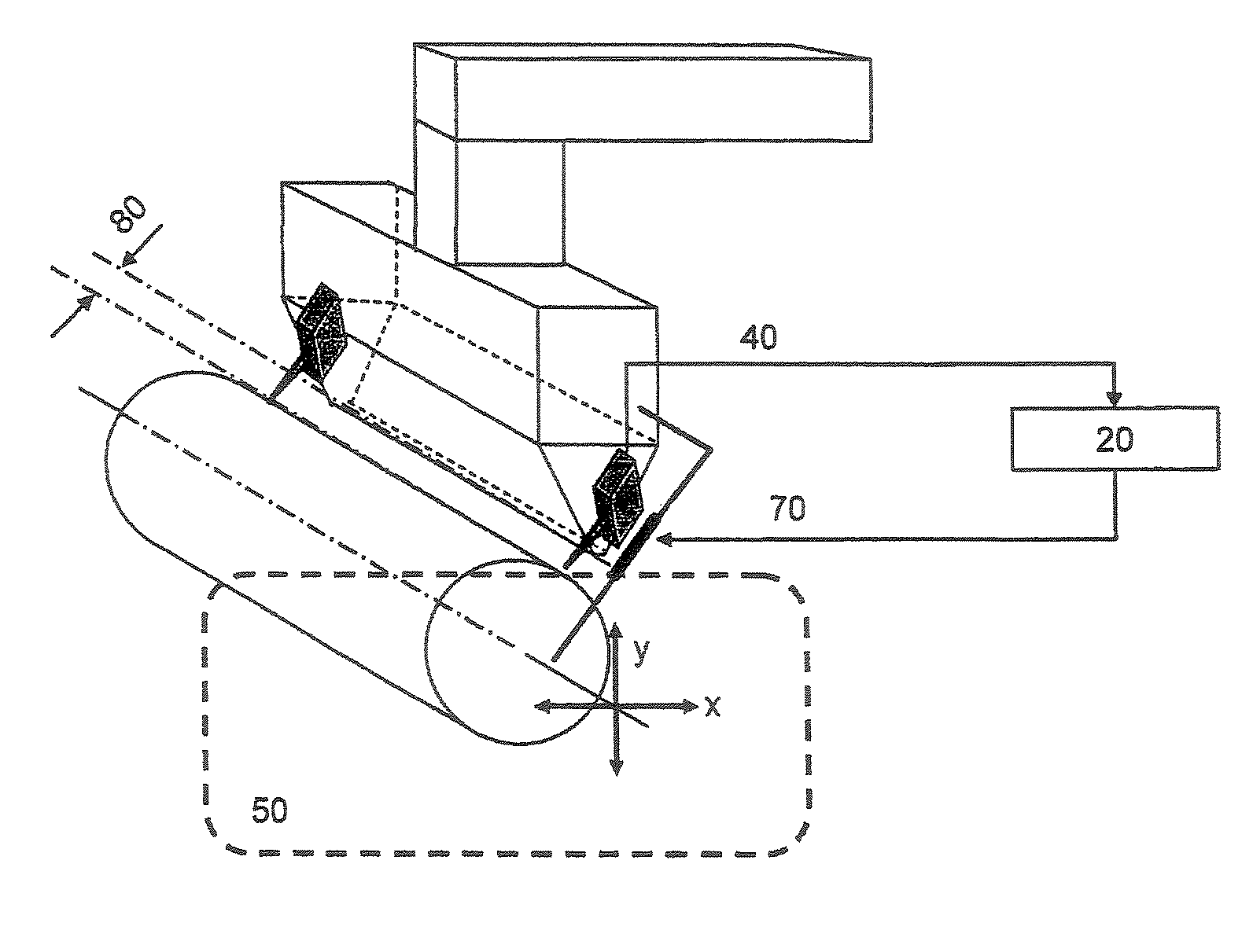
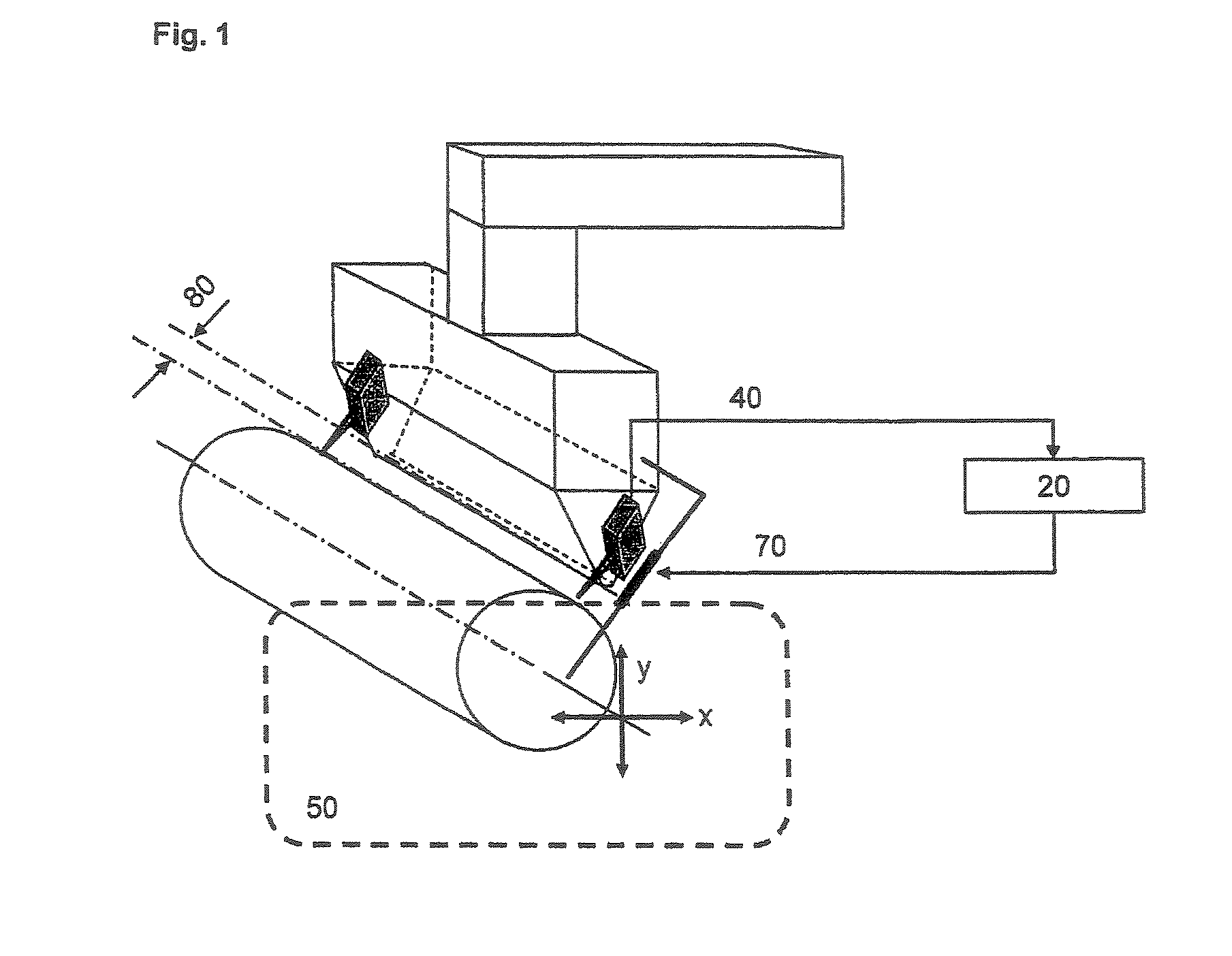
[0082]A chill roll has been positioned centrally at a distance of 25 mm from the discharge orifice of the slot extrusion die. The diameter of the roll is 400 mm and its width is ...

##ventive example 2

Inventive Example 2

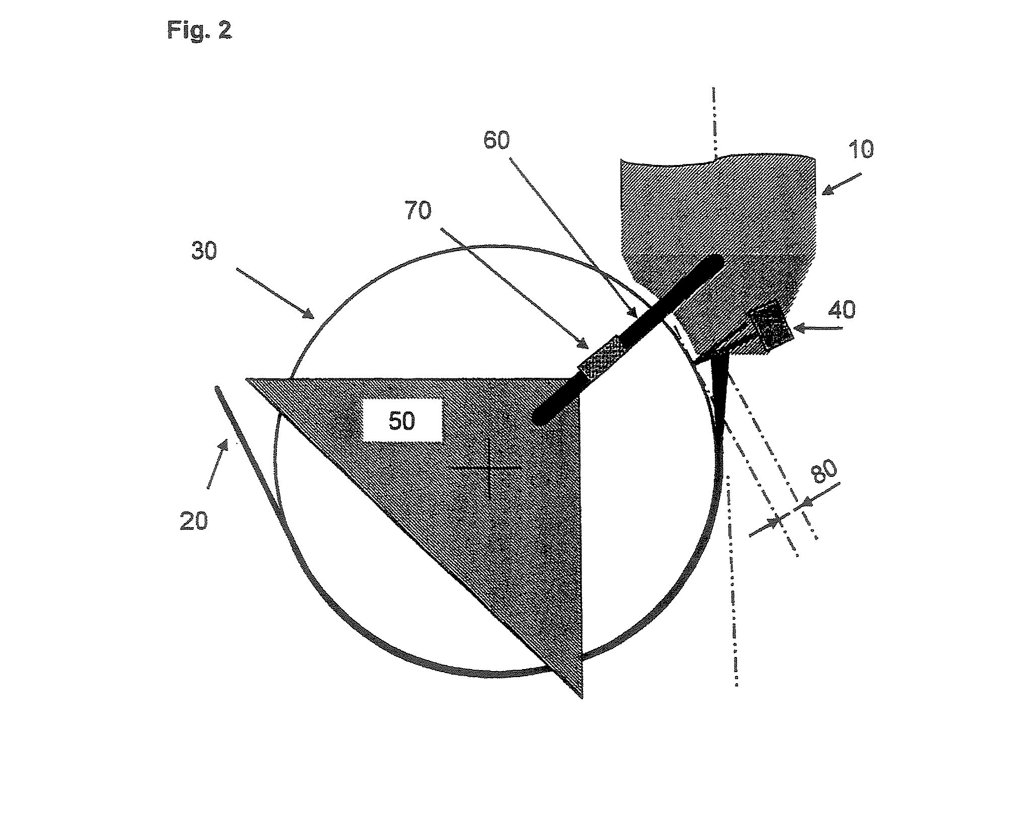
[0089]Inventive Example 2 differs from Inventive Example 1 in that the extrusion die has connection to the roll frame at two points on the right-hand and left-hand side of the discharge orifice of the extrusion die, by way of piezoactuators. The piezoactuators are controlled by way of a control circuit integrated into the optical distance measurement system, and actively counteract changes in distance between the extrusion-die discharge orifice and the cooled roll (chill roll).

##ventive example 3

Inventive Example 3

[0090]Inventive Example 3 differs from Inventive Example 2 in that the radius of the die lip in the discharge region is about 25 μm, its radius uniformity across the width being + / −1 μm (sharp edge).

[0091]The relevant variables for the foils obtained in Comparative Example 1 and in Inventive Examples 1-3 are determined using stamped-out circular sections whose diameter is 12 cm, and are collated in the table below.

[0092]

ComparativeInventiveInventiveInventiveExample 1Example 1Example 2Example 3Solid connection−+++between die andcasting rollSolid connection +−−++actuatorsSharp edge−−−+Foil thickness90909090[average value in μm]Oscillations between602454die and casting roll[+−μm]Optical path difference129810(in-plane)[average value in nm]Laser deflection0.90.50.50.4[angular minutes]Thickness tolerance20.90.50.3Ø 12 cm [%]Vertical birefringence0.00030.00030.000290.00025(− without, + with)


PUM

PropertyMeasurementUnit
distanceaaaaaaaaaa
roughness depths Raaaaaaaaaaa

Abstract

The invention relates to a method for producing a thermoplastic plastic film. According to said method, the thermoplastic plastic is melted and transported in an extrusion installation comprising an extruder, an extrusion nozzle with a wide-slot delivery opening and a chill roll, which is fixed to a roll system and then leaves the delivery opening of the extrusion nozzle in the form of a flat melted web. Said melted web is then applied to the chill roll and is cooled. The invention is characterised in that it uses an extrusion installation, in which the distance between the delivery opening of the extrusion nozzle and the surface of the cooled roll does not vary by more than + / −50 μm during the operating time. The invention also relates to a film of this type and to uses of the latter.

Description

[0001]The invention relates to a process for production of a foil composed of thermoplastic, to a foil, and to use of the foil.BACKGROUND OF THE INVENTION[0002]EP 1 117 731 B1 describes polycarbonate foils which are almost optically isotropic, and also a chill-roll process for their production. The foils are composed of linear or branched polycarbonate whose average molecular weight Mw is from 10,000 to 40,000. Inventive foils can by way of example have shrinkage of <1% / <1% (190° C. / 30 min machine direction (MD) / transverse direction (TD)). There is preferably no region of the surface of the inventive foil that deflects linearly polarized light by more than 2 angular minutes. By way of example the path difference can be 31 nm, the birefringence delta n 4×10⁻⁴. By way of example, the tensile strain at break measured to ISO 527-3 MD / TD in the tensile test is 39 and, respectively, 35%. To avoid die lines or extrusion streaks it is recommended that the inner surface of the extrusio...

Claims


Application Information

Patent Timeline
Patent Type & Authority Patents(United States)
IPC IPC(8): B32B37/00B29D11/00B29C48/08B29C48/30B29C48/305B29C48/35B29C48/38B29C48/92
CPCB29C47/0021B29C47/92B29C47/8845B29C2947/92076B29C2947/92152B29C2947/922B29C2947/92247B29C2947/92314B29C2947/92409B29C2947/92428B29C2947/92447B29C2947/92571B29C2947/92647B29C2947/92695B29C2947/92704B29C2947/92809B29C2947/92904B29C2947/92923B29K2025/00B29K2027/06B29K2033/12B29K2055/02B29K2067/00B29K2069/00B29K2105/256B29C47/14B29C48/92B29C2948/92409B29C2948/92704B29C48/08B29C48/305B29C48/914B29C2948/92076B29C2948/92152B29C2948/922B29C2948/92247B29C2948/92314B29C2948/92428B29C2948/92447B29C2948/92571B29C2948/92647B29C2948/92695B29C2948/92809B29C2948/92904B29C2948/92923
Inventor GUENANTEN, CLAUDESTEINFELS, CHRISTOPHGROOTHUES, HERBERTKROHMER, CHRISTOPHHAERING, HELMUTBIRTH, DETLEFNEUROTH, CHRISTOPHERMEIER-KAISER, MICHAELMEON, WALTER
Owner ROHM GMBH
Why Eureka
Try Eureka