
Device for cooling slots of a turbomachine rotor disk

a technology of rotor disk and cooling slot, which is applied in the direction of liquid fuel engines, vessel construction, marine propulsion, etc., can solve the problems of affecting the good operation of the disk and the lifetime of the disk, and achieve the effects of reducing the flow section, increasing the life of the disk, and reducing the air flow section

Active Publication Date: 2012-01-10
SN DETUDE & DE CONSTR DE MOTEURS DAVIATION S N E C M A
View PDF7 Cites 6 Cited by
  • Summary
  • Abstract
  • Description
  • Claims
  • Application Information

AI Technical Summary

Benefits of technology

The present invention proposes a device for improving the cooling of the slots in a turbomachine rotor disk to increase its lifetime. The device includes a rotor disk with slots, a retaining annulus, and air admission orifices. The retaining annulus has a flange that extends upstream from the disk and co-operates with the disk to form a cooling air diffusion cavity. The downstream end of the cavity includes means for reducing the flow rate of air penetrating into the slots in the disk that are in register with the air admission orifices. This results in a uniform cooling for all the slots in the disk, increasing its lifetime. The device also includes a turbomachine with the cooling device.

Problems solved by technology

Nevertheless, that type of cooling circuit does not enable completely uniform cooling to be obtained for all of the slots in the rotor disk, which is harmful for good operation of the disk, and thus for the lifetime of the disk.

Method used


Image

  • Device for cooling slots of a turbomachine rotor disk
  • Device for cooling slots of a turbomachine rotor disk
  • Device for cooling slots of a turbomachine rotor disk

Examples


Embodiment Construction

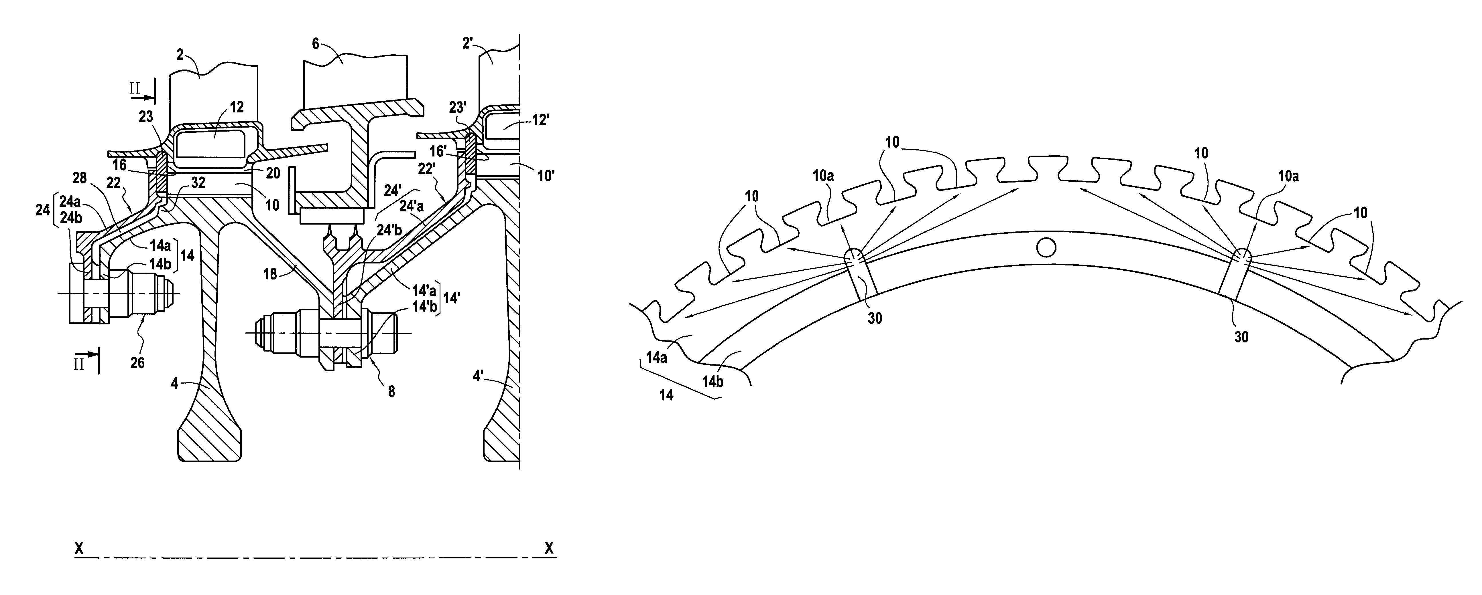
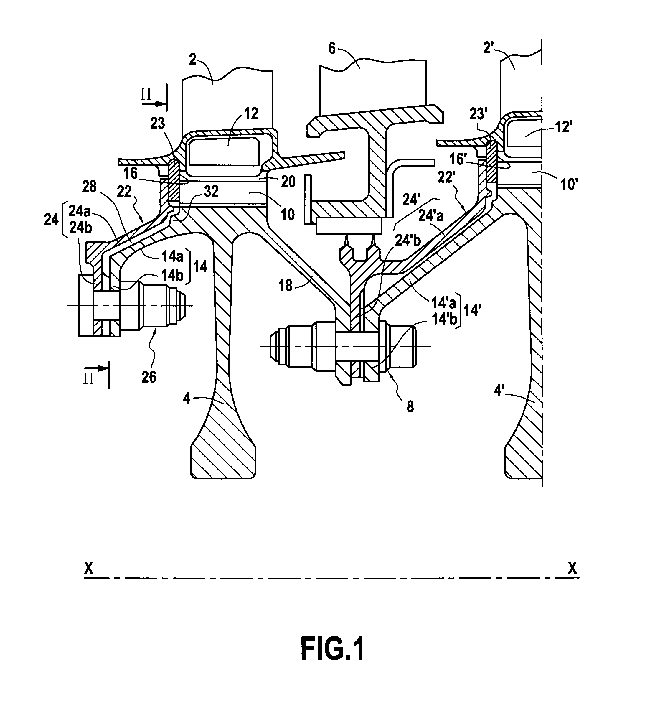
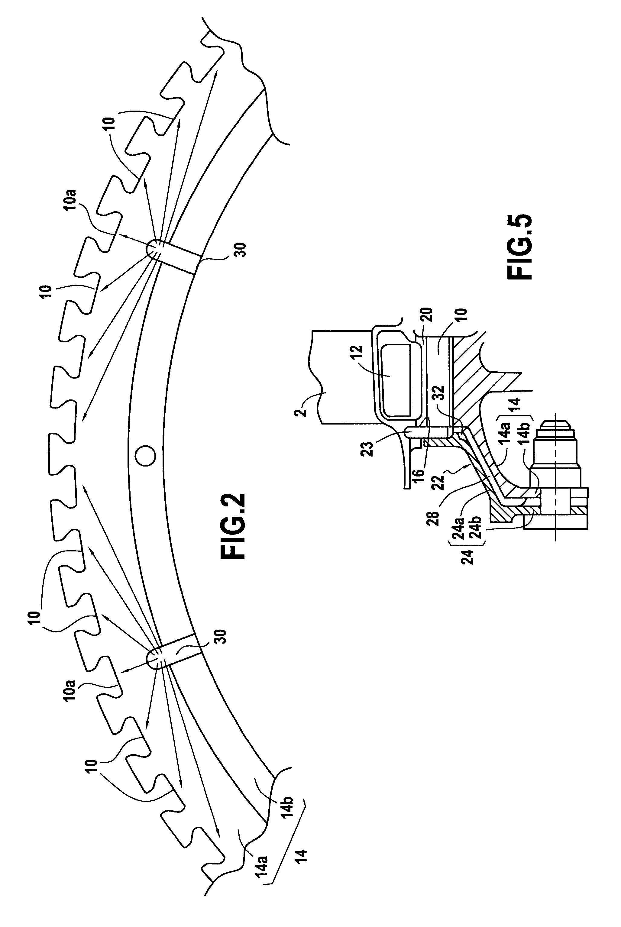
[0027]FIG. 1 is a fragmentary longitudinal section view of a low pressure turbine of an aviation turbomachine fitted with a device constituting an embodiment of the invention.

[0028]Naturally, the present invention applies to any other turbomachine unit (aviation or terrestrial) that has a rotor disk with slots in which blade roots are mounted axially.

[0029]FIG. 1 shows more precisely the first stage and the second stage of the low pressure turbine. The first stage comprises a rotor wheel made up of a plurality of rotor blades 2 mounted axially on a rotor disk 4. The second stage comprises a nozzle made up of a plurality of stator vanes 6 and a rotor wheel placed behind the nozzle and formed by a plurality of rotor blades 2′ mounted axially on a rotor disk 4′.

[0030]The rotor disks 4 and 4′ of the first and second turbine states are centered on the longitudinal axis X-X of the turbomachine and are fixed to each other by bolted connections 8 that are regularly distributed around the ax...


PUM


Abstract

The invention relates to a device for cooling the slots of a turbomachine rotor disk, the device comprising a rotor disk having a plurality of slots and a flange that extends upstream from a radially upstream face of the disk. The device also comprises a retaining annulus having a flange that is placed around the flange of the disk, co-operating therewith to provide a space forming a cooling air diffusion cavity, said cavity opening out into the bottom of each of the slots of the disk, and a plurality of air admission orifices opening out into the diffusion cavity at the upstream end thereof, the cavity having means at its downstream end for reducing the flow rate of air penetrating into the slots of the disk that are situated radially in register with air admission orifices.

Description

BACKGROUND OF THE INVENTION[0001]The present invention relates to the general field of turbomachine rotor disks that are provided at their peripheries with slots in which blade roots are mounted. The invention relates more particularly to a device enabling such slots to be cooled effectively.[0002]In known manner, the disks of a turbomachine rotor, such as the disks in the various stages of the low pressure turbine, include at their periphery a plurality of substantially axial slots into which the roots of moving blades of the turbine are engaged.[0003]While the turbomachine is in operation, the flow section of the low pressure turbine in which the blades are disposed passes gas at a temperature that is very high. The slots in the disk that receive the blade roots are therefore directly exposed to the hot gas so it is necessary to cool them in order to avoid any damage to the disks.[0004]For this purpose, it is known to take a fraction of the air that flows outside the flow section ...

Claims


Application Information

Patent Timeline
Patent Type & Authority Patents(United States)
IPC IPC(8): F01D5/08
CPCF01D5/081Y02T50/676Y02T50/60
Inventor DEJAUNE, CLAUDE GERARD RENEGROS, VALERIE ANNIELORO, GAELSOUPIZON, JEAN-LUC
Owner SN DETUDE & DE CONSTR DE MOTEURS DAVIATION S N E C M A
Learn More