Eureka AIR delivers breakthrough ideas for toughest innovation challenges, trusted by R&D personnel around the world.

Monocrystalline semiconductor wafer comprising defect-reduced regions and method for producing it

a semiconductor wafer and defect reduction technology, applied in the field of monocrystalline semiconductor wafers, can solve the problems of poor reliability, problems in the reliability of gate oxides, and the best semiconductor wafers known at the moment, and achieve the effect of higher defect density

Active Publication Date: 2012-01-03
SILTRONIC AG
View PDF20 Cites 22 Cited by
  • Summary
  • Abstract
  • Description
  • Claims
  • Application Information

AI Technical Summary

Benefits of technology

[0002]The invention relates to a monocrystalline semiconductor wafer having regions with a very low and homogeneous density of GOI-relevant defects. The invention also relates to a method for annealing GOI-relevant defects in a monocrystalline semiconductor wafer, wherein at least one side of the semiconductor wafer is irradiated by means of a laser.

Problems solved by technology

It has been found, however, that even the best semiconductor wafers known at the present time pose problems in specific applications, such as, for example, SOI (Silicon On Insulator), Strained Silicon or sSOI (strained Silicon On Insulator), associated with line widths (design rule) <100 nm during production or during operation of the components.
Thus, leakage currents, short circuits, deviating diode characteristic curves, hot spots, gate oxide failure or poor reliability of the components lead to failure.
It is thus described that ingrown vacancy clusters lead to problems in the reliability of the gate oxide [K. Yamabe, K. Taniguchi, Y. Matsushita, in PROC.
These problems are aggravated with increasing structure miniaturization—particularly when the vacancy clusters reach the magnitude of typical component magnitudes such as e.g. gate lengths.
The semiconductor wafers mentioned above can only inadequately meet the demands imposed by future generations of components, in particular as far as the areal and local properties of the defect homogeneity are concerned.

Method used


Image

  • Monocrystalline semiconductor wafer comprising defect-reduced regions and method for producing it
  • Monocrystalline semiconductor wafer comprising defect-reduced regions and method for producing it
  • Monocrystalline semiconductor wafer comprising defect-reduced regions and method for producing it

Examples


Embodiment Construction

)

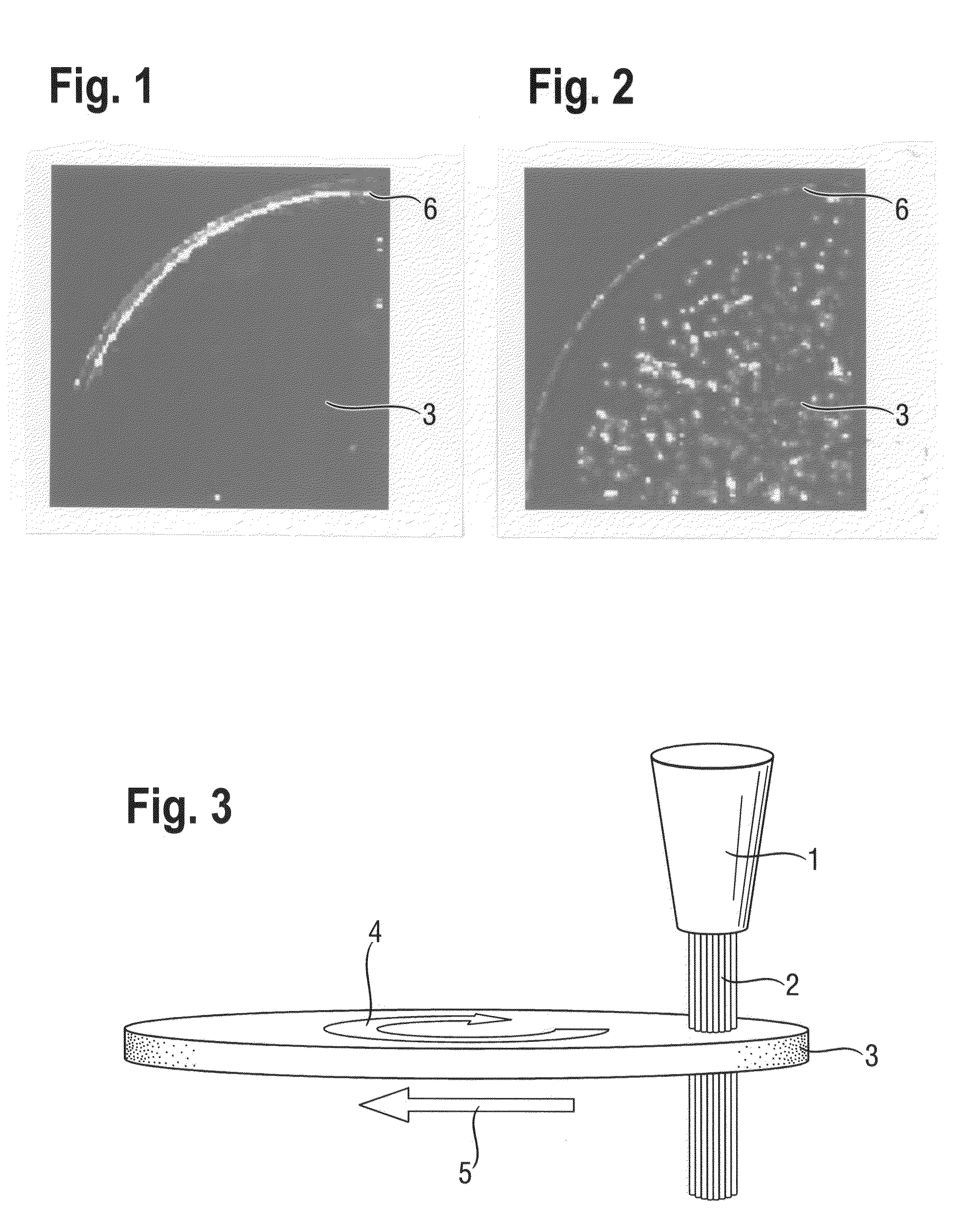
[0016]The term “GOI relevant” defects denotes all defects which adversely affect the quality of a gate oxide produced at the corresponding location. The density of the GOI relevant defects is preferably measured with the aid of the method of IR-Lock-In thermography disclosed in DE19835616A1, since this method enables large-area detection of precisely those defects which cause GOI defects. Thus, in contrast to conventional GOI tests, even very low defect densities of 0.1 / cm2, for example, can be determined quantitatively.

[0017]By contrast, other detection methods such as e.g. laser scanning methods by which the entire wafer surface is examined for defects are significantly less well suited since although the defects detected by said methods can lead to a failure of a component, they need not necessarily lead to such failure. Defects that have no influence on the GOI-quality, such as e.g. particles adhering to the surface, are also detected. On the other hand, in the production of mi...


PUM

PropertyMeasurementUnit
temperatureaaaaaaaaaa
wavelengthaaaaaaaaaa

Abstract

Monocrystalline semiconductor wafers have defect-reduced regions, the defect-reduced regions having a density of GOI-relevant defects within the range of 0 / cm2 to 0.1 / cm2 and occupy overall an areal proportion of 10% to 100% of the planar area of the semiconductor wafer, wherein the remaining regions of the semiconductor wafer have a significantly higher defect density than the defect-reduced regions. The wafers may be produced by a method for annealing GOI relevant defects in the wafer, by irradiating defined regions of a side of the semiconductor wafer by laser wherein each location is irradiated with a power density of 1 GW / m2 to 10 GW / m2 for at least 25 ms, wherein the laser emits radiation of a wavelength above the absorption edge of the wafer semiconductor material and wherein the temperature of the wafer rises by less than 20 K as a result of irradiation.

Description

BACKGROUND OF THE INVENTION[0001]1. Field of the Invention[0002]The invention relates to a monocrystalline semiconductor wafer having regions with a very low and homogeneous density of GOI-relevant defects. The invention also relates to a method for annealing GOI-relevant defects in a monocrystalline semiconductor wafer, wherein at least one side of the semiconductor wafer is irradiated by means of a laser.[0003]2. Background Art[0004]Semiconductor wafers, in particular silicon wafers, are generally used for producing microelectronic components. In the semiconductor industry, and in particular in silicon technology, which has advanced very far scientifically and also technologically, the quality requirements of the semiconductor wafers increase further and further as time goes on, in view of the ever further decreasing smallest feature sizes of the microelectronic components.[0005]In order to meet these requirements, several types of very low-defect semiconductor wafers were develop...

Claims


Application Information

Patent Timeline
Patent Type & Authority Patents(United States)
IPC IPC(8): C30B29/02
CPCH01L21/268H01L29/32Y10T428/24802Y10T428/31678H01L21/20
Inventor KNERER, DIETERHUBER, ANDREASLAMBERT, ULRICHPASSEK, FRIEDRICH
Owner SILTRONIC AG
Why Eureka
Eureka Blog
Learn More