
Top operating telescoping adjustable valve box and valve stem assembly

a technology of telescopic adjustment and valve stem, which is applied in the direction of valve housing, valve operating means/releasing devices, transportation and packaging, etc., can solve the problems of buried valves, buried valves, piping, damage to service boxes, etc., and achieve the effect of preventing unauthorized activation of pentagon keys

Active Publication Date: 2011-12-27
WHITE DENNIS WAYNE +1
View PDF34 Cites 25 Cited by
  • Summary
  • Abstract
  • Description
  • Claims
  • Application Information

AI Technical Summary

Benefits of technology

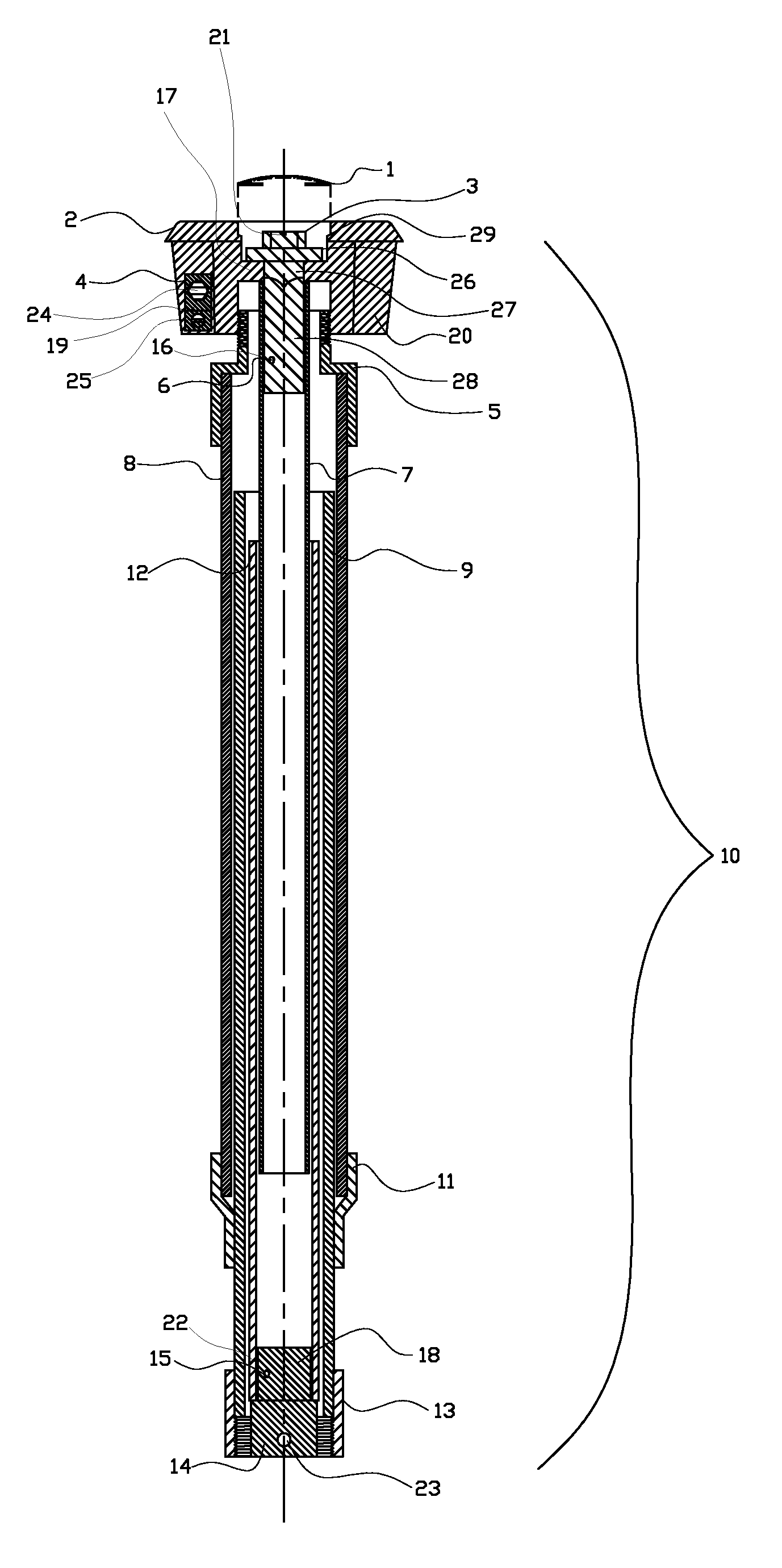
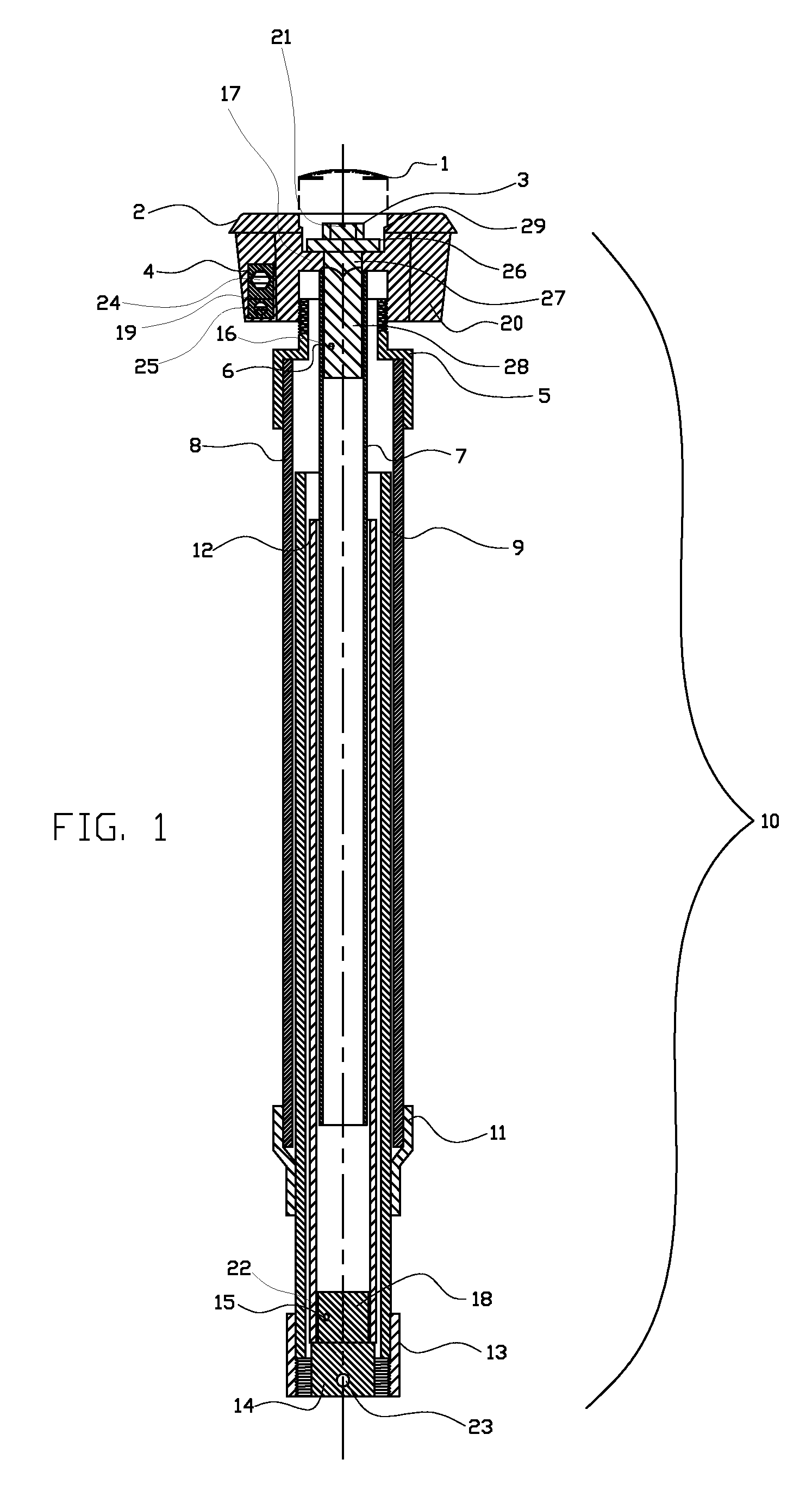
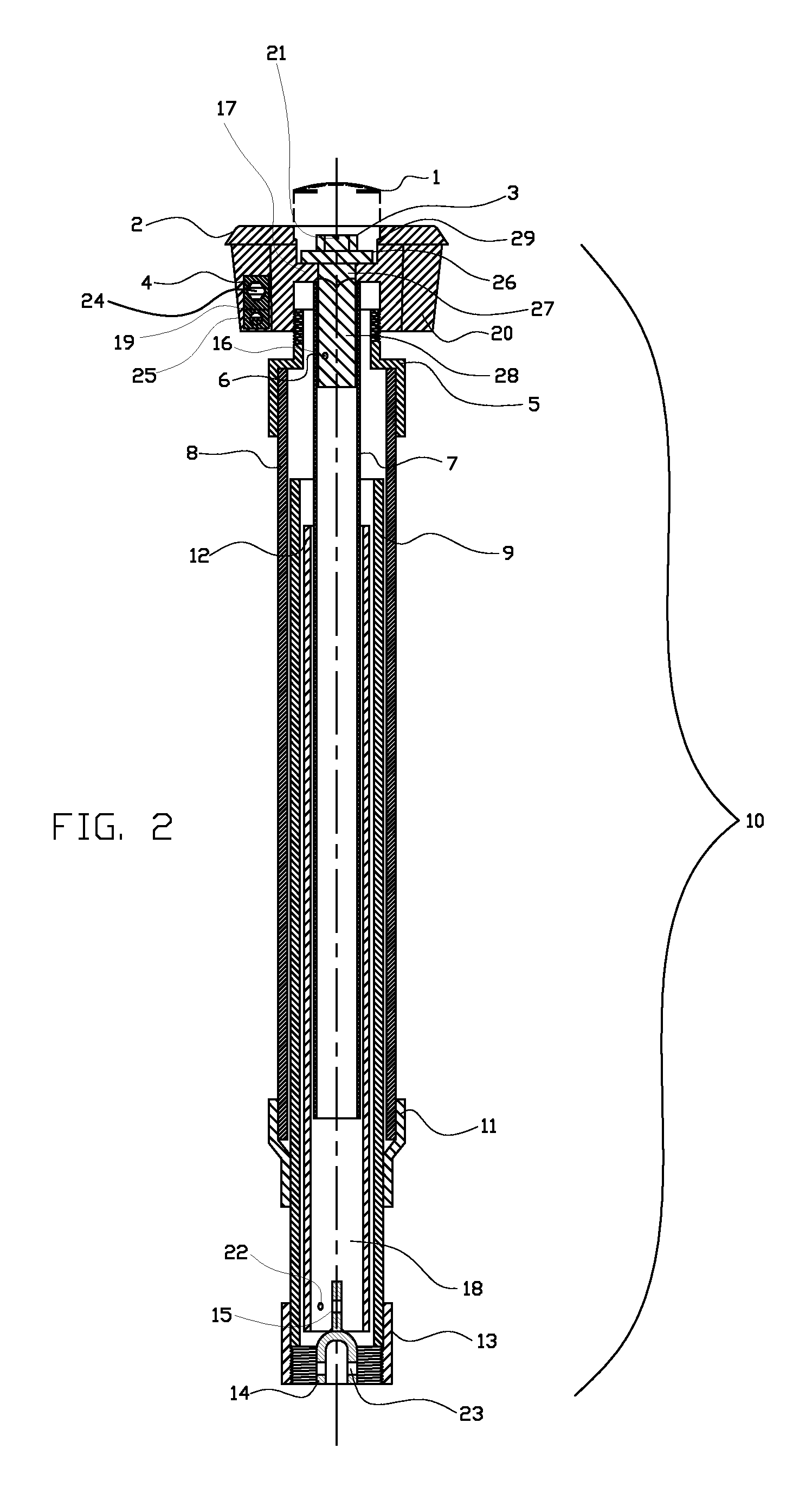
[0010]The curb service box assembly of the present invention incorporates features to improve effectiveness over currently known assemblies in use. The assembly of the invention also provides top ground actuation of a Minneapolis pattern valve, allowing a pentagon key system to operate from the top of the unit at ground level. The key connects to an upper square stainless steel stem tube that extends down to a larger square stainless steel stem tube. A valve receiver adapter inserts into the bottom of the lower square stainless steel stem tube. The valve receiver connects to a buried, Minneapolis style, curb stop valve by means of a fastener, such as a cotter pin. The curb stop valve is actuated by turning the AWWA #1 pentagon, located on top of unit, which actuates the nut head on the curb stop valve. Both upper and lower sections of the square stainless steel stem tubes are housed inside of the upper and lower section of the outer PVC barrel pipe. The upper and lower sections of the PVC barrel pipe thus act as a conduit for the upper and lower sections of square stainless steel stem tubes. The upper and lower barrel sections and the square stainless steel stem tubes telescope simultaneously with each other, allowing for a large range of vertical adjustability.
[0011]The vertical adjustability, along with the simultaneous telescoping capability, allows for a free-floating unit between the upper and lower sections of the valve box unit. The free-floating nature of this invention allows the upper section to separate from the bottom section when an upward force is applied. The separation occurs at midpoint of the valve box unit without damaging the lower section of the valve box unit, buried valve, or buried piping.
[0013]Additional features of the invention include a tracer block terminal for the use of pipe location and a tamper proof cap used to prevent unauthorized operation of the buried valve operating stem assembly. The top base of the valve box system has a round casted metal top with two protruding wings, located on opposite sides of each other. The wings are situated on the underneath side of the metal top. A tracer block terminal attaches to one wing. The tracer block terminal allows for the attachment of tracing wire from the service pipeline to the valve box top base. This provides the ability to locate the service pipeline, whether the pipe used is conductive or non-conductive. No additional devices are required to accommodate the use of tracing wire.
[0014]A center positioned machined ledge on the top base accepts an optional tamper-proof cap. The cap is a round metal disk, and when inserted into the machined ledge, prevents unauthorized activation of the pentagon key. The cap is a one-time use part of the valve box system, due to the need to puncture and damage the cap for removal. The valve box top base design accepts replacement caps, as needed.

Problems solved by technology

This method can prove to be difficult if debris has entered the conduit or soil pipe and does not allow the wrench to extend to the valve nut.
With service boxes of this type, unauthorized persons may remove the plug or top and actuate the valve nut and replace the plug or top, and the controlling authority would not be aware of the action taken.
Any upward force applied to the top of the curb box, after installation, may result in damage to the service box, buried valve, and piping.
This can cause installation difficulty for the buried pipe and valve when trying to maintain proper expansion depth, as top ground conditions change.
In addition, locating a service line can prove to be virtually impossible if no tracing system has been installed, and the design of currently known boxes does not provide for any practical or effective means of locating the service line.

Method used


Image

  • Top operating telescoping adjustable valve box and valve stem assembly
  • Top operating telescoping adjustable valve box and valve stem assembly
  • Top operating telescoping adjustable valve box and valve stem assembly

Examples


Embodiment Construction

[0027]Referring initially to FIG. 1, shown in cross-section, is the top operating telescoping adjustable valve box and telescoping valve stem assembly, indicated generally at 10, of the preferred embodiment of the invention.

[0028]One feature of the preferred embodiment of the invention utilizes a means of actuating from ground level a buried Minneapolis pattern service valve. Such valves serve water service lines extending from the service valve connection to an end point (i.e. building or structure). The Minneapolis pattern valve is not shown, but such valves are well known and common in the industry and have mechanical pipe threads atop the valve body, which allows connection of the Minneapolis pattern valve to the service curb box.

[0029]The top base 2 of the assembly 10 is of casted metal with two side tab wings 20 180° apart located on the underneath side of the round top of base 2. As shown in FIG. 1, the top base 2 has a machined hole in the center for the acceptance of the pe...


PUM


Abstract

A top operating telescoping adjustable valve box and valve stem assembly that incorporates a telescoping valve stem actuating system which, when coupled to a service valve, allows for the operation from ground level without the removal of a plug or lid. The system has a large range of vertical adjustability. The upper and lower sections of the assembly are in frictional connection with each other, which allows no transmittal of force to the lower section when any upward force to the upper section is applied, thus reducing damage to the buried valve and pipeline. The assembly provides a tracing block terminal, located on the top base, to allow for the connection of tracing wire from the valve top to the service pipe for service line location. The assembly also incorporates the placement of a tamper proof cap for the prevention of unauthorized operation of valve stem system.

Description

[0001]This application claims priority under 35 USC 119 to Provisional Patent Application Ser. No. 61 / 102,035 filed on Oct. 2, 2008, the contents of which are hereby incorporated by reference.BACKGROUND OF THE INVENTION[0002]1. Field of the Invention[0003]This invention relates to a valve or curb service box assembly for buried service valves (Minneapolis pattern), operated from ground level.[0004]2. Description of Related Art[0005]Current valve or curb service boxes connect to service valves buried below ground level. These valves control the flow through a buried pipeline connected to the valve. Access to the buried valve is by means of a conduit or soil pipe used to accept a wrench of sufficient length to extend down through the pipe for the coupling of the wrench to the valve nut, and then turned to operate the valve for an open or closed effect.[0006]Some valves or curb service boxes have an extension rod already coupled to the valve nut which rod extends a short distance upwar...

Claims


Application Information

Patent Timeline
Patent Type & Authority Patents(United States)
IPC IPC(8): F16K51/00
CPCF16K27/006F16K31/46Y10T137/7014Y10T137/7017
Inventor WHITE, DENNIS WAYNEJACOBS, JOHN LEONARD
Owner WHITE DENNIS WAYNE
Learn More