
Digital video physical layer using a multi-level data code

a data code and digital video technology, applied in the field of apparatus and methods for communicating data, can solve the problems of significant processing overhead and unsuitable replacement ofphanse, and achieve the effect of extending the range availabl

Active Publication Date: 2011-12-20
CRESTRON ELECTRONICS
View PDF6 Cites 8 Cited by
  • Summary
  • Abstract
  • Description
  • Claims
  • Application Information

AI Technical Summary

Benefits of technology

The present invention provides a new physical layer for transmitting data, control, and BIT signals in a digital visual interface (DVI) system. This new layer uses a multiple level symbol system with a low clock rate, which allows for a wider range of high definition television cabling. The invention also includes a method for transmitting and receiving the signals associated with the TMDS physical layer. Additionally, the invention provides a digital interface adapted to transmit signals over a predetermined distance using four twisted wire pairs. The technical effects of the invention include extending the range of high definition television cabling and improving the transmission of data, control, and BIT signals in the DVI system.

Problems solved by technology

Phanse is not applicable as a replacement for TMDS because it does not have enough bandwidth for the highest video rates and because it relies on recovering the clock from the data stream, has a significant DC residual correction required, and requires echo cancellation circuitry due to the duplex nature of its anticipated communication path.
However, Deloit requires that delimiters be inserted between multi-level symbol groups which introduces a significant processing overhead that is not desirable when associated with high speed video data transfer.

Method used


Image

  • Digital video physical layer using a multi-level data code
  • Digital video physical layer using a multi-level data code
  • Digital video physical layer using a multi-level data code

Examples


Embodiment Construction

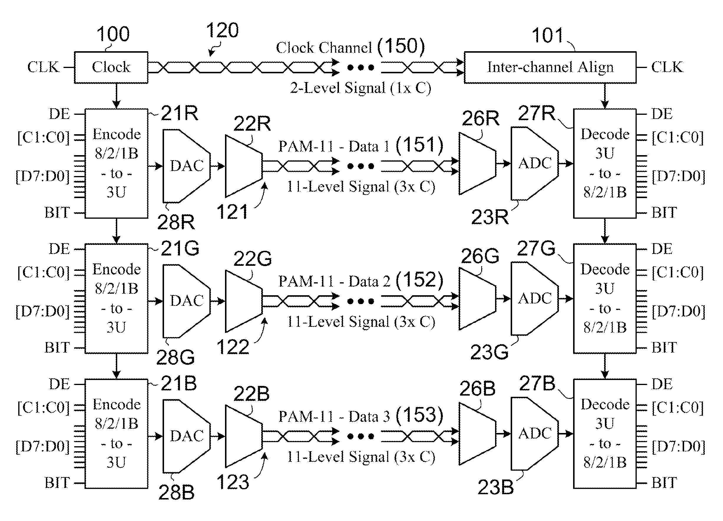
[0030]The present invention is a digital interface physical layer suitable for use in high-speed digital communications.

[0031]Unless the context clearly requires otherwise, throughout the description and the claims, the words ‘comprise’, ‘comprising’, and the like are to be construed in an inclusive sense as opposed to an exclusive or exhaustive sense; that is to say, in the sense of “including, but not limited to”.

MODE(S) FOR CARRYING OUT THE INVENTION

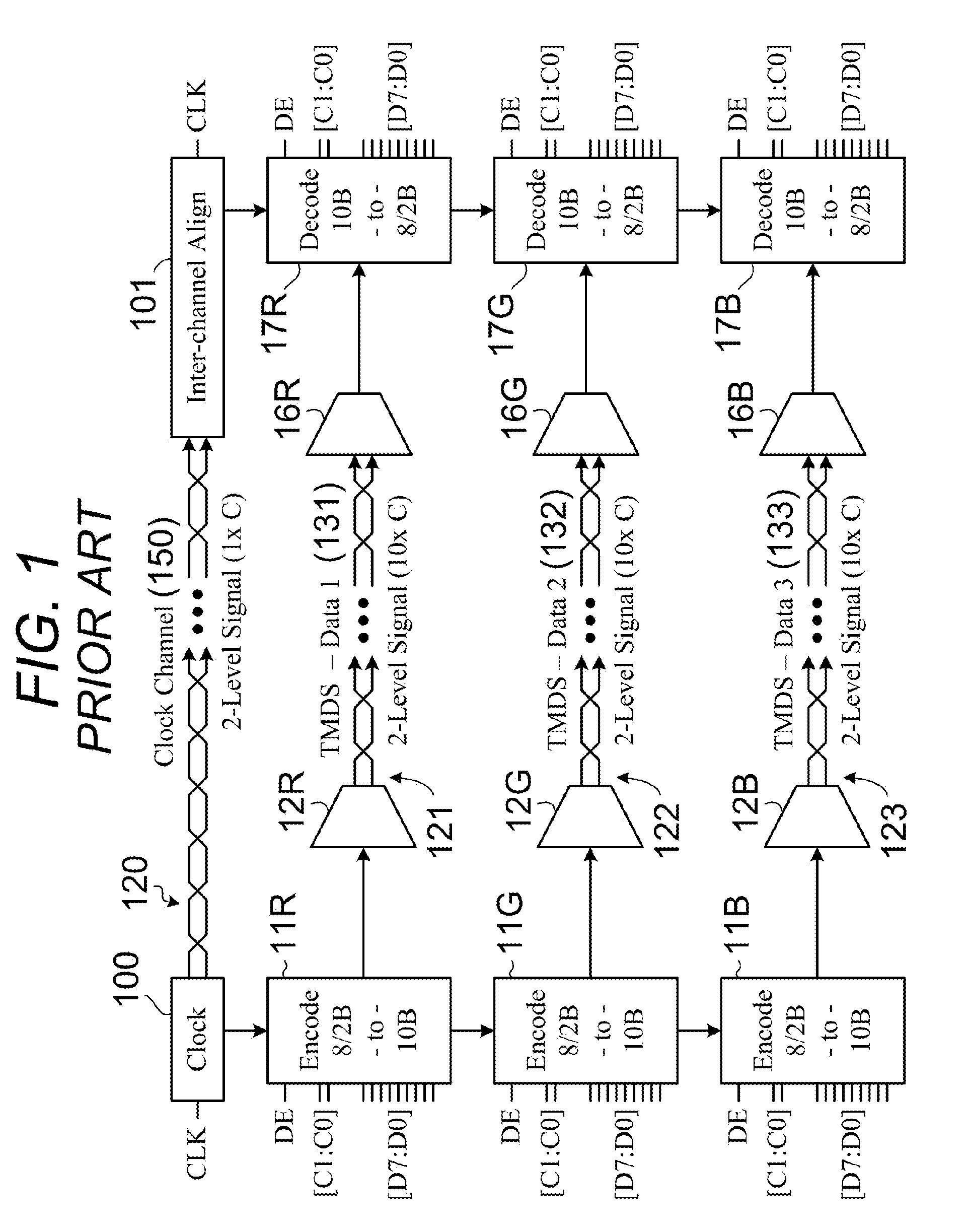
[0032]The preferred embodiment of the present invention is described herein in the context of a an interface circuit and cabling that replaces the Transition Minimized Differential Signaling (TMDS) physical layer used in both the Digital Visual Interface (DVI) and High Definition Multimedia Interface (HMDI), which are widely used in consumer electronics.

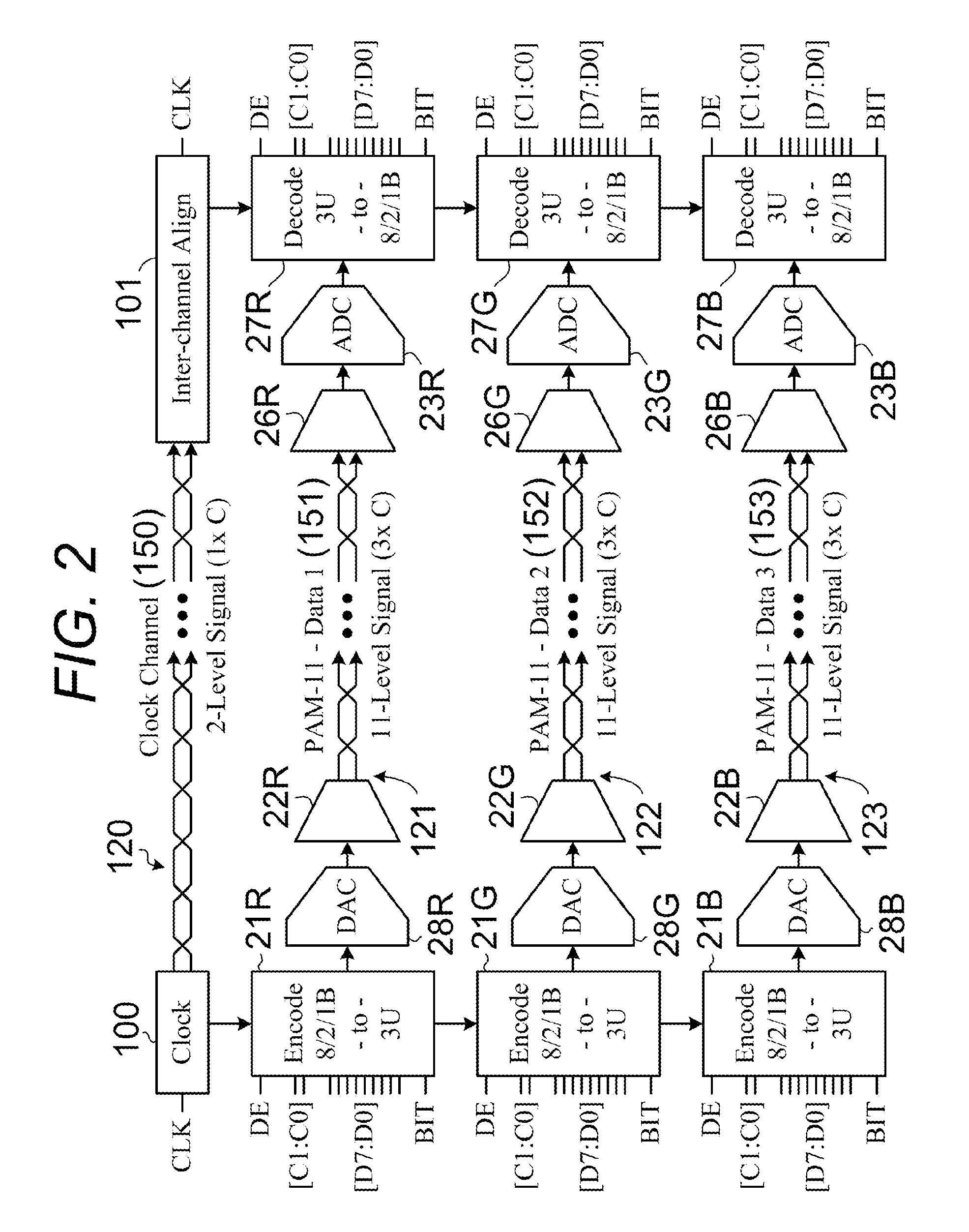
[0033]Refer now to FIG. 2 and continue to refer to FIG. 1. One embodiment of the present invention is a ‘pin-compatible’ replacement for the well-known TMDS interfaces. For example, bo...


PUM


Abstract

Digital video data is transmitted from a video source (61) to a video sink (62) as a group of three multilevel symbols (611, 612, and 613) per pixel color with each associated symbol being sent at a rate of three times the pixel clock (601). When eleven levels are used per symbol (611) and undesirable symbol groups having excess DC residual or minimal energy are eliminated, and a built-in-test symbol group is added for pixel alignment; there results a one-to-one correspondence between the remaining symbol groups available and the two-hundred and sixty possible states that are used in the TMDS physical layer that is in widespread commercial use.

Description

BACKGROUND OF THE INVENTION[0001]1. Technical Field[0002]This invention relates to apparatus and methods for communicating data, and more specifically communicating data over a plurality of channels, such as a cable having a plurality of conductors (for example, four twisted pairs of wires), and for encoding and / or decoding data in connection with such communications.[0003]2. Background Art[0004]FIG. 1 illustrates the prior art transition minimized differential signaling (TMDS) physical layer that was developed by Silicon Image Inc. as a member of the Digital Display Working Group and is used in both the well-known Digital Visual Interface (DVI) and High Definition Multimedia Interface (HMDI).[0005]TMDS is a physical layer technology for transmitting high-speed serial data in a simplex mode from one transmitter to one receiver. A useful description of this TMDS interface is included in the background section of Hwang (U.S. Pat. No. 7,359,437). The TMDS transmitter incorporates a cod...

Claims


Application Information

Patent Timeline
Patent Type & Authority Patents(United States)
IPC IPC(8): H04B3/50H04L25/49H03M7/00
CPCH03M5/145H04N21/43632H04L25/49H04N21/4122H04L25/0272G09G5/008G09G2370/12
Inventor KIRKPATRICK, PHILIP L.
Owner CRESTRON ELECTRONICS
Learn More