Liquid crystal composition and liquid crystal display device
a liquid crystal display and composition technology, applied in the direction of thin material processing, instruments, chemistry apparatus and processes, etc., can solve the problem of long service life of the devi
- Summary
- Abstract
- Description
- Claims
- Application Information
AI Technical Summary
Benefits of technology
Problems solved by technology
Method used
Image

Examples
example 1
[0084]Example 1 was prepared so that the first component herein is 20% by weight or more from the basis of the composition of the comparative example 1. The ratio of the second component to the fifth component herein was same as that of the Comparative Example 1. The composition had the following components and characteristics. Δ∈ of Example 1 was lager than that of Comparative Example 1. NI of Example 1 was higher than that of Comparative Example 1.
[0085]
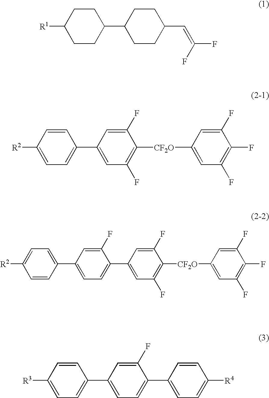
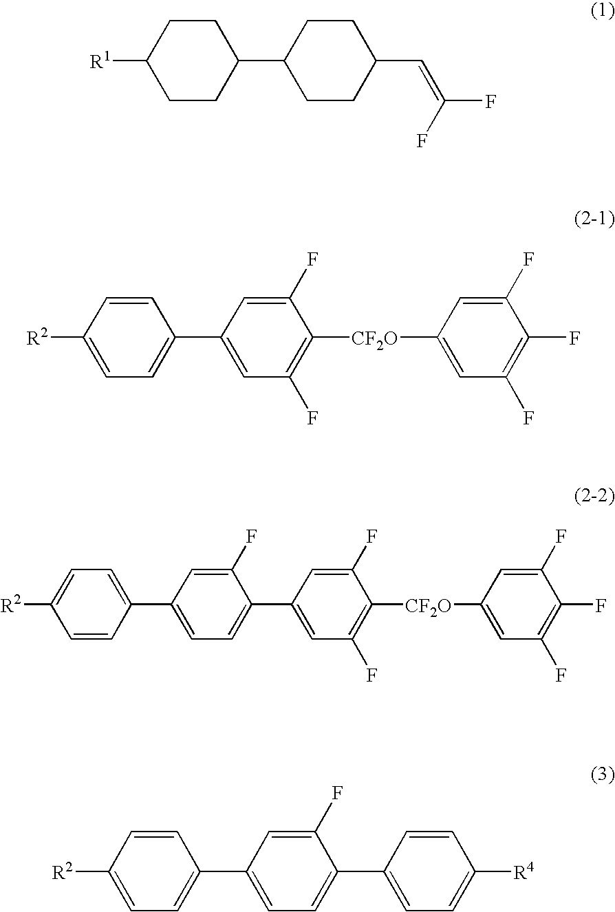
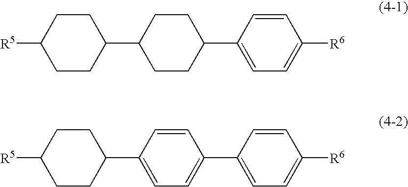
3-HH-VFF(1-1)30%3-BB(F,F)XB(F,F)-F(2-1-1)10%2-BB(F)B-3(3-1)4%2-BB(F)B-5(3-1)6%V-HHB-1(4-1-3)10%3-HHB-O1(4-1-2)2%VFF-HHB-1(4-1-6)2%V-HBB-1(4-2-3)3%2-HBB-F(4-2-4)5%3-HBB-F(4-2-4)5%5-HBB-F(4-2-4)5%5-HXB(F,F)-F(—)2%3-HBB(F,F)-F(—)10%5-H2B(F)-F(—)2%3-HHEH-3(—)2%1O1-HBBH-3(—)2%NI = 87.1° C.;Tc ≦−30° C.;Δn = 0.117;Δε = 4.2;Vth = 2.04 V;γ1 = 69.5 mPa · s;τ = 11.0 ms;VHR-1 = 99.5%.
example 2
[0088]Example 2 was prepared so that the first component herein is 20% by weight or more and the second component herein is 10% by weight from the basis of the composition of the comparative example 2. The ratio of the third component to the fifth component herein was same as that of the Comparative Example 2. The composition had the following components and characteristics. Δ∈ of Example 2 was lager than that of Comparative Example 2.
[0089]
3-HH-VFF(1-1)30%5-HH-VFF(1-1)10%2-BB(F,F)XB(F,F)-F(2-1-1)3%3-BB(F,F)XB(F,F)-F(2-1-1)7%2-BB(F)B-3(3-1)5%3-HBB(F,F)XB(F,F)-F(—)5%3-HB(F)B(F,F)XB(F,F)-F(—)5%3-BB(2F,5F)B-3(—)5%3-HB-CL(—)5%3-HB-O2(—)5%7-HB-1(—)5%1V2-BB-CL(—)5%5-HBB(F)B-2(—)5%5-HB(F)BH-3(—)5%NI = 63.6° C.;Tc ≦−20° C.;Δn = 0.110;Δε = 4.9;Vth = 1.73 V;γ1 = 55.1 mPa · s;τ = 9.8 ms;VHR-1 = 99.1%.
example 3
[0092]Example 3 was prepared so that the second component herein is 10% by weight from the basis of the composition of the comparative example 3. The ratio of the first component, the third component to the fifth component herein was same as that of the comparative example 3. The composition had the following components and characteristics. A of Example 3 was lager than that of Comparative Example 3.
[0093]
3-HH-VFF(1-1)37%3-BB(F,F)XB(F,F)-F(2-1-1)11%5-BB(F)B(F,F)XB(F,F)-F(2-2-1)5%1-BB(F)B-2V(3-2)7%2-BB(F)B-2V(3-2)4%V2-BB(F)B-1(3-3)7%3-HBB-2(4-2-1)3%1V-HBB-2(4-2-3)4%3-HHXB(F,F)-F(5-1)3%3-HH-4(—)5%5-HH-V(—)5%3-HB-CL(—)3%3-HB-O2(—)3%5-HBB(F)B-3(—)3%NI = 73.4° C.;Tc ≦−20° C.;Δn = 0.127;Δε = 4.4;Vth = 1.97 V;γ1 = 50.4 mPa · s;τ = 6.9 ms;VHR-1 = 99.0%.
PUM
| Property | Measurement | Unit |
|---|---|---|
| temperature | aaaaa | aaaaa |
| temperature | aaaaa | aaaaa |
| response time | aaaaa | aaaaa |
Abstract
Description
Claims
Application Information
 - Generate Ideas
- Intellectual Property
- Life Sciences
- Materials
- Tech Scout
- Unparalleled Data Quality
- Higher Quality Content
- 60% Fewer Hallucinations
Browse by: Latest US Patents, China's latest patents, Technical Efficacy Thesaurus, Application Domain, Technology Topic, Popular Technical Reports.
© 2025 PatSnap. All rights reserved.Legal|Privacy policy|Modern Slavery Act Transparency Statement|Sitemap|About US| Contact US: help@patsnap.com