
Multi-user MIMO-SDMA for finite rate feedback systems

a feedback system and multi-user technology, applied in the field of information processing, can solve the problems of increasing the challenge of improving spectrum usage efficiency, difficult to accurately measure the channel information or associated channel characteristics, and limited electromagnetic frequency spectrum capacity

Active Publication Date: 2011-12-06
APPLE INC
View PDF49 Cites 46 Cited by
  • Summary
  • Abstract
  • Description
  • Claims
  • Application Information

AI Technical Summary

Problems solved by technology

Wireless communication systems transmit and receive signals within a designated electromagnetic frequency spectrum, but the capacity of the electromagnetic frequency spectrum is limited.
As the demand for wireless communication systems continues to expand, there are increasing challenges to improve spectrum usage efficiency.
However, it is difficult to accurately measure the channel information or associated channel characteristics (such as SINR or channel quality information (CQI)) for a particular receiver when the communication status of other receivers in the vicinity is not known.
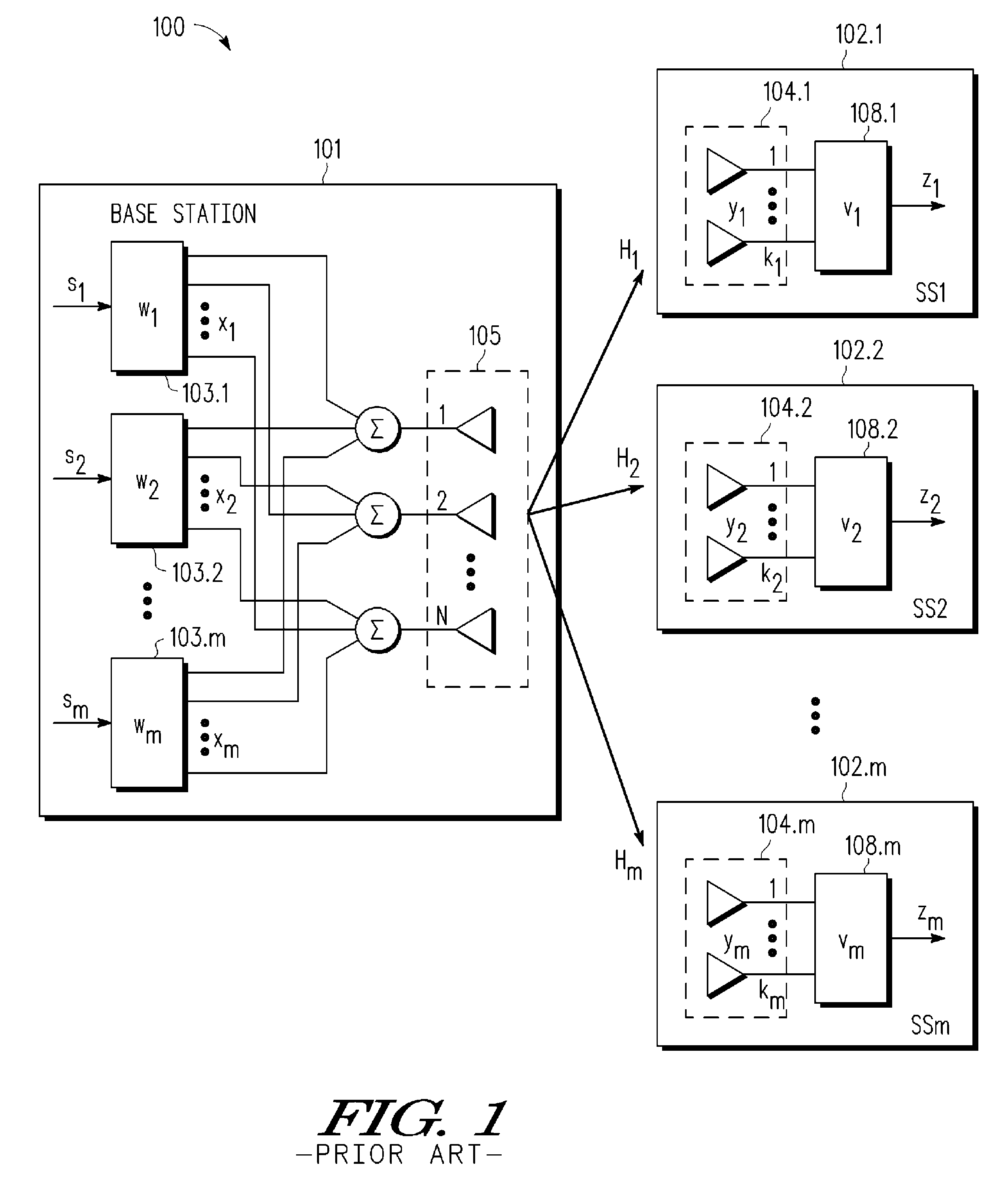
In an SDMA system, this results from the fact that signal information being sent to other receivers can appear as interference or noise at the intended receiver 102.i, though the receiver can not be expected to have this knowledge when the channel characteristics are being measured.
Another difficulty associated with channel feedback techniques is the large overhead required for providing full channel feedback.
However, the quantization techniques used in existing codebook systems to compress the channel feedback information can introduce inaccuracies in the feedback signal, causing losses in the zero-forcing / interference reduction properties of MU-MIMO beamforming.
Feedback quantization also causes inaccuracies when the base station uses an estimate of the channel quality indicator (like SINR) that is computed at the receiver, which leads to loss in performance.
Moreover, the limited feedback resources require that any practical system be designed to have a low feedback rate, and existing codebook systems can have unacceptably high feedback data rates.

Method used


Image

  • Multi-user MIMO-SDMA for finite rate feedback systems
  • Multi-user MIMO-SDMA for finite rate feedback systems
  • Multi-user MIMO-SDMA for finite rate feedback systems

Examples


Embodiment Construction

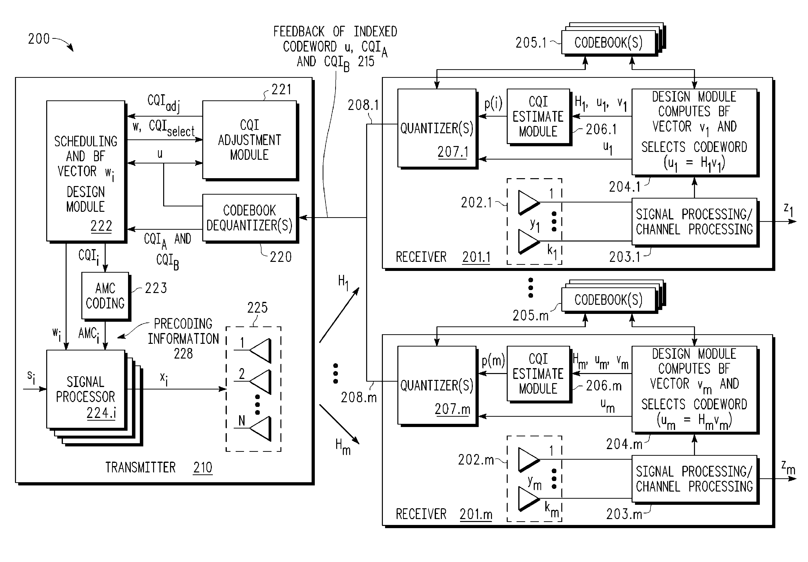
[0020]A finite rate feedback system and methodology are described for use in efficiently providing precoder feedback in wireless, multi-user, multi-input, multiple output (MIMO) SDMA systems. Using codebook-based preceding techniques, multi-user beamforming transmission is enabled by accurately estimating and adjusting one or more CQI values for each receiver based upon the optimized receive beamforming vector designed at each receiver. In various example embodiments, a receiver estimates the CQI value(s) by jointly designing a receive beamforming vector v and selecting a corresponding codeword u=Hv which are optimized to correspond to the MIMO channel between the transmitter and the receiver. The receive beamforming vector v and corresponding codeword u may be optimized by maximizing a predetermined metric ρ for estimating the signal-to-interference-and-noise (SINR) or other CQI information detected at the receiver in a multi-user setting without any knowledge of the other users or...


PUM


Abstract

A multi-user MIMO downlink beamforming system with limited feedback (200) is provided to enable preceding for multi-stream transmission, where a channel codeword (ui) and one or more channel quality indicator values (CQIA, CQIB) are computed at the user equipment (201.i) on the basis of maximizing a predetermined SINR performance metric (ρi) which estimates the receive signal-to-noise-ratio (SINR) at the user equipment (201.i). The computed codeword (ui) and CQI values (or differential values related thereto) are quantized and fed back to help the base station (210) which applies a correction to the appropriate CQI value in the course of designing the transmit beamforming vectors w and determining the appropriate modulation and coding level to be used for downlink data transmission.

Description

BACKGROUND OF THE INVENTION[0001]1. Field of the Invention[0002]The present invention is directed in general to field of information processing. In one aspect, the present invention relates to a system and method for signal processing and control signaling for wireless MIMO communication systems.[0003]2. Description of the Related Art[0004]Wireless communication systems transmit and receive signals within a designated electromagnetic frequency spectrum, but the capacity of the electromagnetic frequency spectrum is limited. As the demand for wireless communication systems continues to expand, there are increasing challenges to improve spectrum usage efficiency. To improve the communication capacity of the systems while reducing the sensitivity of the systems to noise and interference and limiting the power of the transmissions, a number of wireless communication techniques have been proposed, such as Multiple Input Multiple Output (MIMO), which is a transmission method involving mult...

Claims


Application Information

Patent Timeline
Patent Type & Authority Patents(United States)
IPC IPC(8): H04B7/02
CPCH04B7/0417H04B7/0634H04B7/0632H04B7/0857H04B7/086H04L5/14H04W88/02H04W88/08
Inventor MUNDARATH, JAYAKRISHNAN C.KOTECHA, JAYESH H.
Owner APPLE INC
Learn More