
Local emergency isolation valve controller with diagnostic testing and trouble indicator

a technology of isolation valve controller and diagnostic testing, which is applied in the direction of service pipe system, water main, gas/liquid distribution and storage, etc., can solve the problems of indicator lamp activation, indicator lamp burnout, indicator lamp activation, etc., and achieve the effect of evaluating the performance of the overall safety of the instrumented system with more accuracy

Inactive Publication Date: 2011-12-06
SAUDI ARABIAN OIL CO
View PDF30 Cites 17 Cited by
  • Summary
  • Abstract
  • Description
  • Claims
  • Application Information

AI Technical Summary

Benefits of technology

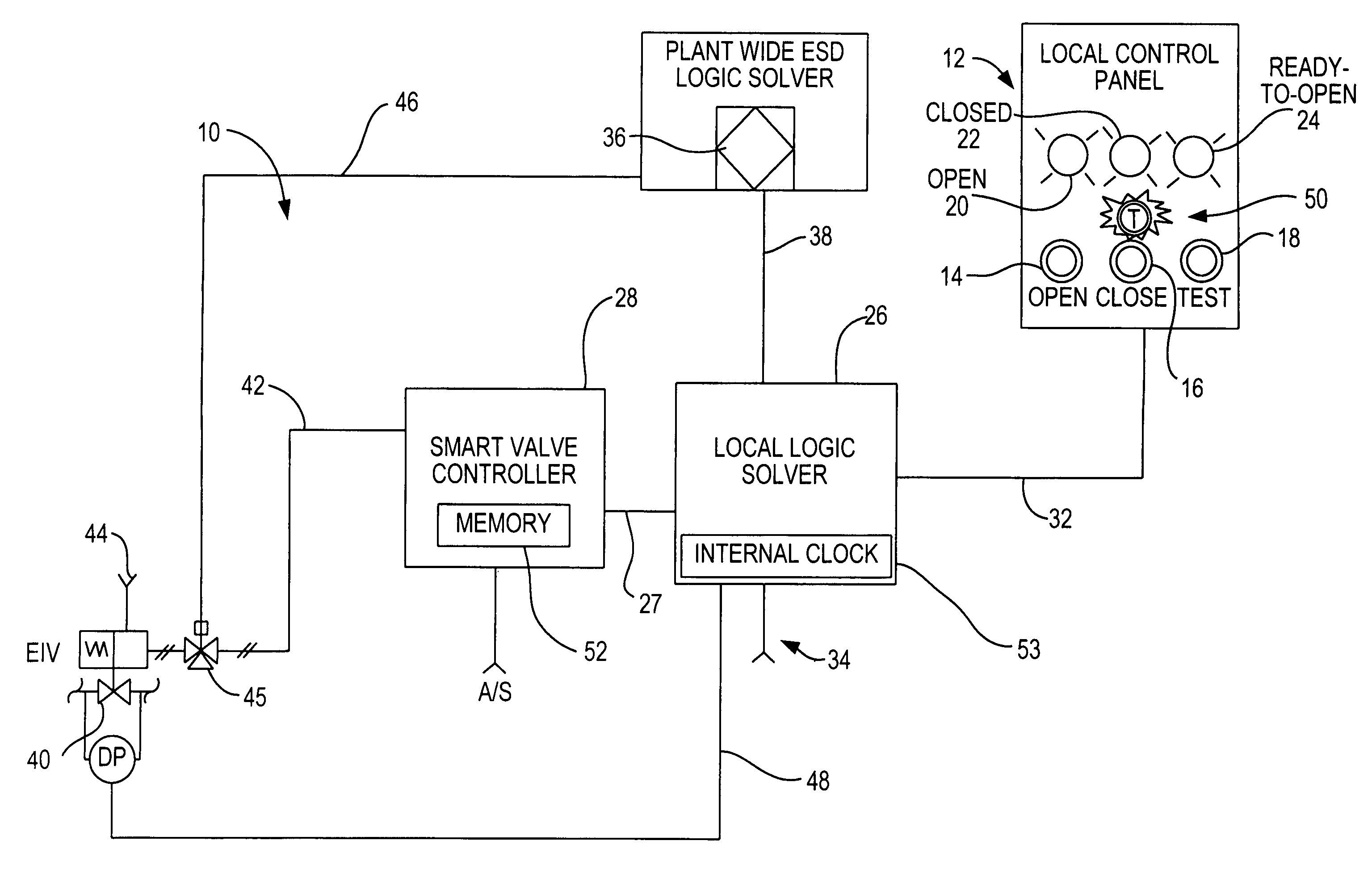
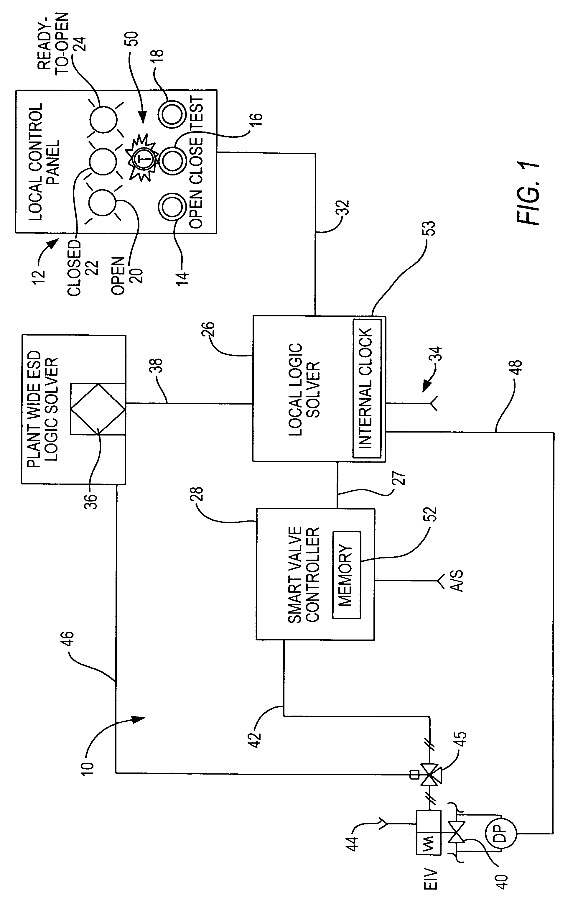
The present invention expands the capabilities of smart valve controllers to include logic and local interface capabilities required to perform a safety instrumented function associated with an emergency isolation valve within the smart valve controller. It also incorporates a timeclock and recording capability to record faults and other valve performance data. The invention provides an indicator light that alerts operators to a problem locally, allowing them to perform necessary safety precautions and alert a specialist to further diagnose the problem. The invention monitors and indicates only dangerous, normally undetected failures which would disable the intended safety functions, with such monitoring and indication being provided with a local indicator to personnel in the field. The invention helps perform the required documentation of system performance and can record valve performance data such as the date and time at which a fault is detected, the fault is cleared, a stroke test is initiated, the stroke test pass or fail result is attained, a safety system demand is issued, or a nuisance trip occurs.

Problems solved by technology

In addition, when the normally steady ON indicator light is in a steady OFF state, the illumination device such as a lamp of the indicator light has either burned out or the device being monitored is out of service.
Further, a common trouble indicator lamp will be activated upon the occurrence of a significant fault, such as a stuck valve, broken shaft, or a condition in which damage to the valve actuator would prevent the EIV from moving to a pre-defined fail-safe state.

Method used


Image

  • Local emergency isolation valve controller with diagnostic testing and trouble indicator
  • Local emergency isolation valve controller with diagnostic testing and trouble indicator
  • Local emergency isolation valve controller with diagnostic testing and trouble indicator

Examples


Embodiment Construction

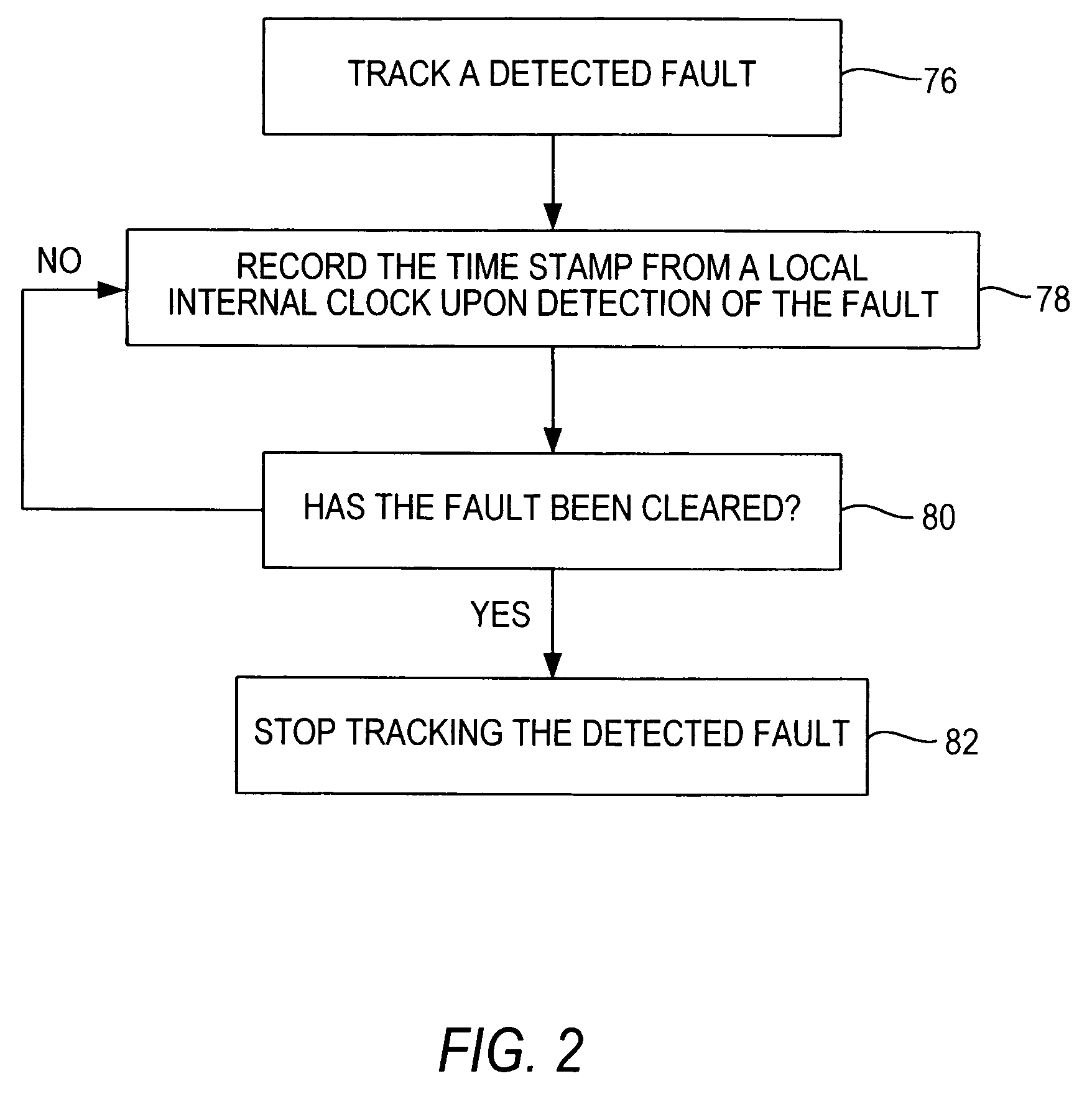
[0039]As illustrated in FIGS. 1 and 2, the present invention is a system and method for managing plant processes which include enhanced function indicators and logic and local interface capabilities in a smart valve controller, such that a monitoring system of a process plant is capable of performing safety instrumented functions (SIF) with an emergency isolation valve (EIV) within the smart valve controller itself, and so the overhead or footprint of data communications and processing of the plant-wide ESD is reduced, and diagnostic coverage of each EIV as final elements is increased through improved testing features.

[0040]The smart valve controller can be implemented in a known manner, for example, to provide the apparatus described in U.S. Pat. No. 6,186,167 and U.S. Patent Application publication no. US 20030062494 A1, each of which is incorporated by reference in its entirety.

[0041]Such an implementation of the integrated function indicator and smart controller reduces the plan...


PUM


Abstract

A local logic solver that operates with a local smart valve controller to control, test and monitor performance characteristics of a local field-mounted emergency isolation valve device, outputting a local indication of trouble on the device, which is mounted in the field away from the facility's central control panel for the process. The local logic solver includes a recording function and memory for retrieval of detected faults that are time-stamped and recorded locally to generate documentation and to track the elapsed time, starting when the degraded state of the device was detected and first signaled as a problem; other performance data is also recorded. Accordingly, the operation of the overall system is simplified by eliminating the need for an external computer to diagnose any problems. A local control panel preferably includes pushbuttons and lights used during routine operations of the valve and a fault indicator light substantially adjacent to or in close proximity to the device being monitored to alert personnel of detected faults.

Description

CROSS-REFERENCES TO RELATED APPLICATIONS[0001]The present invention is a continuation-in-part of “Emergency Isolation Valve Controller With Integral Fault Indicator,” U.S. application Ser. No. 11 / 095,416, filed Mar. 31, 2005, now U.S. Pat. No. 7,504,961, the entire contents of the which is herein incorporated by reference.FIELD OF THE INVENTION[0002]This invention relates to valve controllers, and in particular to a smart valve system for an emergency isolation valve (EIV). The valve controller may be used with pneumatic, hydraulic, or electrically-operated EIVs.BACKGROUND OF THE INVENTION[0003]Known smart valve systems and remote logic solvers can be connected to a plant-wide central monitoring computer, but such a configuration requires significant overhead in communication links among the distributed mechanisms, such as safety devices, in a process plant. Such overhead is compounded because smart valve controllers and local safety logic solvers can be separate entities each used ...

Claims


Application Information

Patent Timeline
Patent Type & Authority Patents(United States)
IPC IPC(8): G08B21/00
CPCF16K37/0083Y10T137/8175Y10T137/8158Y10T137/7761Y10T137/86397
Inventor FLANDERS, PATRICK S.
Owner SAUDI ARABIAN OIL CO
Learn More