
System for detecting and measuring parameters of passive transponders

a technology of passive transponders and parameters, applied in the field of passive transponder parameters detection and measurement systems, can solve the problems of limited battery life of implants, reduced resolution, and reduced detection discrimination, and achieve the effect of greater detection discrimination

Active Publication Date: 2011-12-06
PULSED INDIGO DEV
View PDF27 Cites 237 Cited by
  • Summary
  • Abstract
  • Description
  • Claims
  • Application Information

AI Technical Summary

Benefits of technology

[0025]When used as a “presents” detector, the invention over comes problems pointed out with the prior art, again, by using a single magnetic pulse to activate the transponder and basing detection on the oscillation decay rate of the return signal. By using a single magnetic pulse to excite the transponder, no signal at the center frequency of the transponder is introduced into the system that interferes with the returned signal. This allows the receiver to detect the signal at the transponder's peak excitation. Since the transponders can be tailored to exhibit a specified quality factor within a specified manufacturing band, basing transponder detection on the oscillation decay rate of the excited transponder offers greater detection discrimination. Since the transponder has a known quality factor, the return signal's magnitude should decrease by a fix amount from one cycle to the next. Using a computational unit to measure this rate of decay over several signal cycles and several transponder interrogations allows the computational unit more accurately determine if the return signal is from a transponder or some other source. The process is almost identical to the parametric process except, here the end result is a go / no-go based on the degree of match between the transponders measured quality factor and the expected value.

Problems solved by technology

This limits these inventions as follows:1) When batteries are used, the implant's useful life is limited to the battery life, while the minimum size of the implant is limited by the size of the battery.2) When inductive power is used, the implant must have an induction coil large enough to supply power to the device at a distance from the power source.
A small modulation bandwidth allows for a quicker the scan but lowers the resolution.
A large bandwidth provides more resolution but takes longer and allows more interference in the return signal.
Taken together the result is that even when fully optimized for scan time and resolution the system response time is not capable of capturing some rapidly changing physiological events.
The faults with this strategy are:1) Since the output signal from the transponder starts to decay as soon as the excitation signal is terminated and several cycles are required to dampen the excitation signal, the received signal is be detected when the transponder output is much lower than the peak output.2) The second problem with this invention is the simple threshold detection method.

Method used


Image

  • System for detecting and measuring parameters of passive transponders
  • System for detecting and measuring parameters of passive transponders
  • System for detecting and measuring parameters of passive transponders

Examples


Embodiment Construction

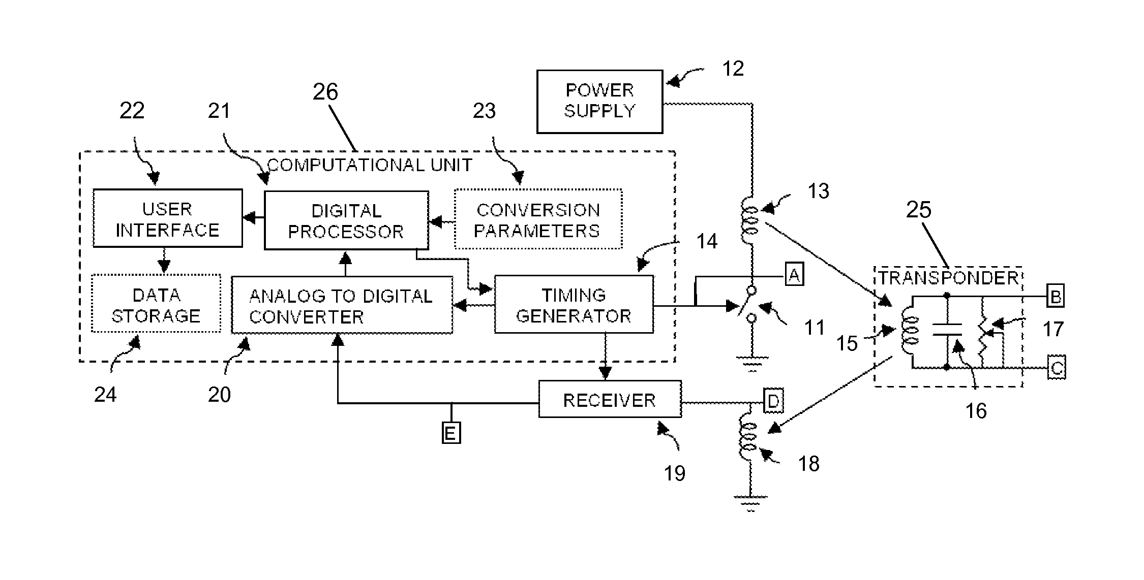
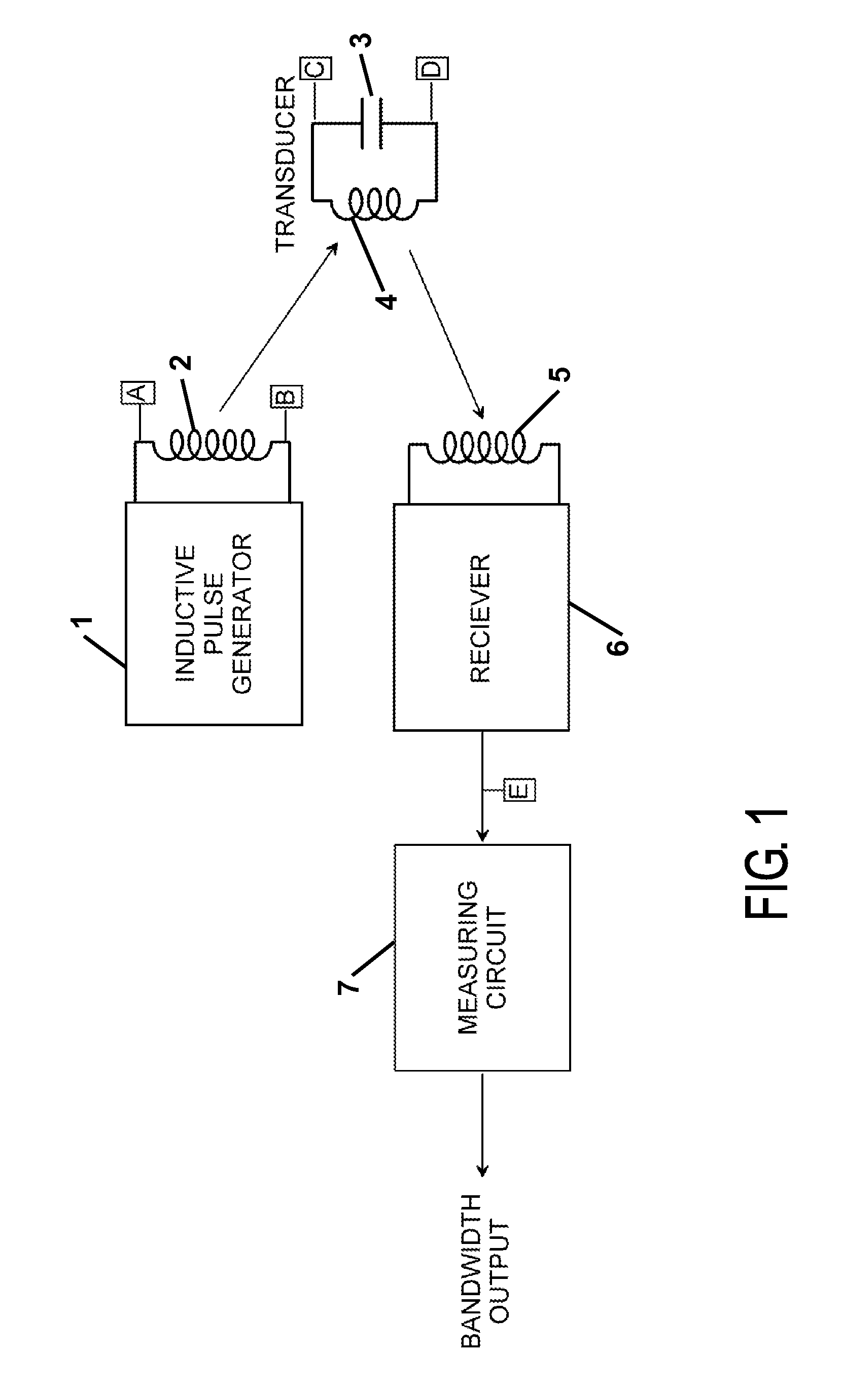
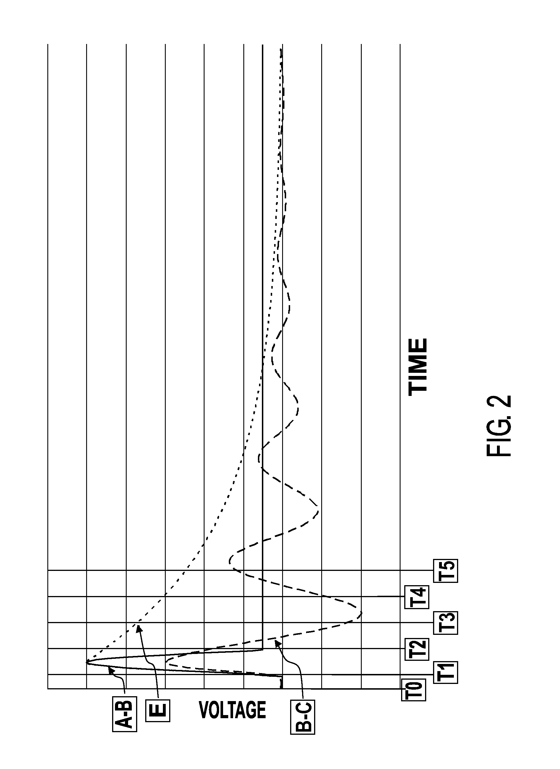
[0032]A block diagram of the overall system is shown in FIG. 1. Points on the diagram where signals of interest are found are marked with the boxed capital letters A through E. The voltage wave forms at these locations are shown under varying conditions in FIG. 2, with the same boxed capital letter annotation.

[0033]The descriptions for each element of FIG. 1 are as follows:[0034]The inductive pulse generator or magneto-strictive transducer 1 switches on a drive voltage across an induction coil 2 causing a current flow to build up in the induction coil 2. The current flowing in the induction coil 2 creates a magnetic field in the space around the induction coil 2. When the current flowing in the coil 2 reaches a maximum value, the inductive pulse generator 1 switches off the drive voltage across the induction coil 2. The removal of the drive voltage across the induction coil 2 causes the magnetic field around the induction coil 2 to rapidly collapse resulting in a high rate of change...


PUM


Abstract

A detection and paramedic measuring system using a transponder composed of passive components and pulse inductive interrogation is disclosed. A methodology based on measuring the quality factor of the transponder is employed to detect a specific species of transponder or measure a parameter that alters the transponders quality factor.

Description

CROSS-REFERENCE TO RELATED APPLICATION[0001]This application claims the filing benefit under 35 U.S.C. §119(e) of U.S. Provisional Application No. 60 / 942,031, filed Jun. 5, 2007, which is herein incorporated by reference.FEDERALLY SPONSORED RESEARCH[0002]Not ApplicableCROSS-REFERENCE TO RELATED APPLICATIONS[0003]Not ApplicableTECHNICAL FIELD[0004]The primary field of application of the invention is the monitoring of physiological parameters or the detection of an object within a living organism.BACKGROUND OF THE INVENTION[0005]In-body wireless communications techniques are limited by the ability of living tissue to conduct electromagnetic energy. The generally accepted range of frequencies wherein attenuation by the tissue is acceptable is 40 kHz to less than 30 MHz. This range is also limited to a subset of frequencies where strong interfering signals such as AM radio, WWV, marine radio, etc. are minimal The practice is further limited by the need for both the transponder and monit...

Claims


Application Information

Patent Timeline
Patent Type & Authority Patents(United States)
IPC IPC(8): H04Q5/22
CPCH04B5/0043H04B5/0068H04B5/0081H04B5/73H04B5/45H04B5/26
Inventor EVERHART, HOWARD RICHARD
Owner PULSED INDIGO DEV
Learn More