
Bone anchor prosthesis and system

a technology of bone anchors and prostheses, applied in the field of bone anchor prosthesis and system, can solve the problems of most costly health problems in society, back pain and spine pathology, and great suffering of victims, and achieve the effect of facilitating the removal and/or insertion of screws and facilitating the removal of screws

Inactive Publication Date: 2011-12-06
SPINECO
View PDF65 Cites 23 Cited by
  • Summary
  • Abstract
  • Description
  • Claims
  • Application Information

AI Technical Summary

Benefits of technology

The design reduces post-operative failure rates, simplifies surgical procedures, and promotes healing by allowing for secure attachment to various components and the use of biological substances and electrical stimulation, thereby improving the stability and effectiveness of spinal fixation systems.

Problems solved by technology

One of the most costly health problems in society involves back pain and pathology of the spine.
These problems can affect individuals of all ages and can result in great suffering to victims.
Such changes can cause painful excessive motion, or collapse of a motion segment resulting in the contraction of the spinal canal and compression of the neural structures, causing debilitating pain, paralysis or both, which in turn can result in nerve root compression or spinal stenosis.
Although this procedure may result in some minor loss and flexibility in the spine, due to the relatively large number of vertebrae, the minor loss of mobility is typically acceptable.
Any infection that occurs around the pedicle screw can slow the healing process and / or damage the bone around the pedicle screw thereby weakening the connection between the bone and pedicle screw.
When a pedicle structure is being inserted during surgery, the proper type of pedicle screw must be inserted and oriented in a precise manner, or the pedicle structure will not fit properly together.
The removal and reinsertion of another type of pedicle screw can result in increase surgery times, potential damage to the bone and / or cartilage and / or other complications.

Method used


Image

  • Bone anchor prosthesis and system
  • Bone anchor prosthesis and system
  • Bone anchor prosthesis and system

Examples


Embodiment Construction

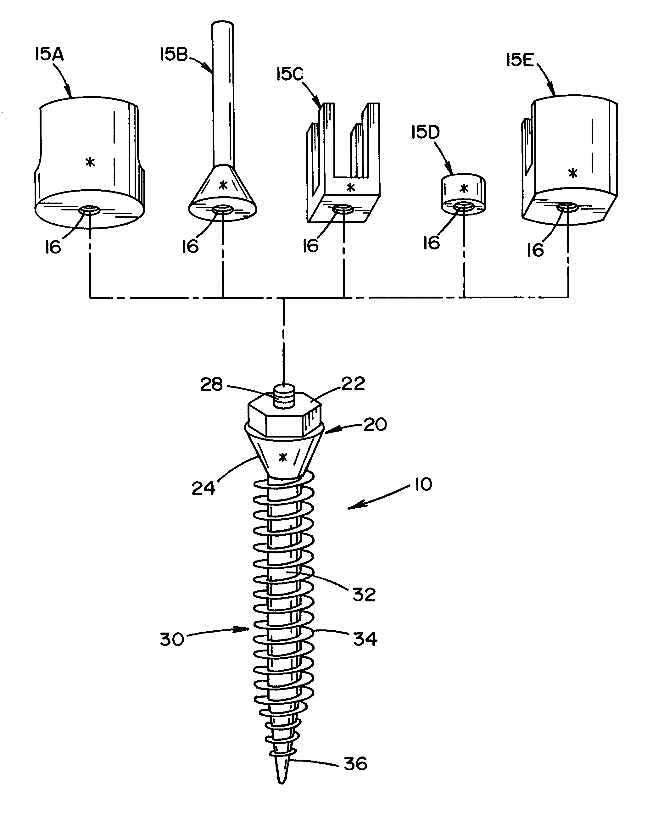
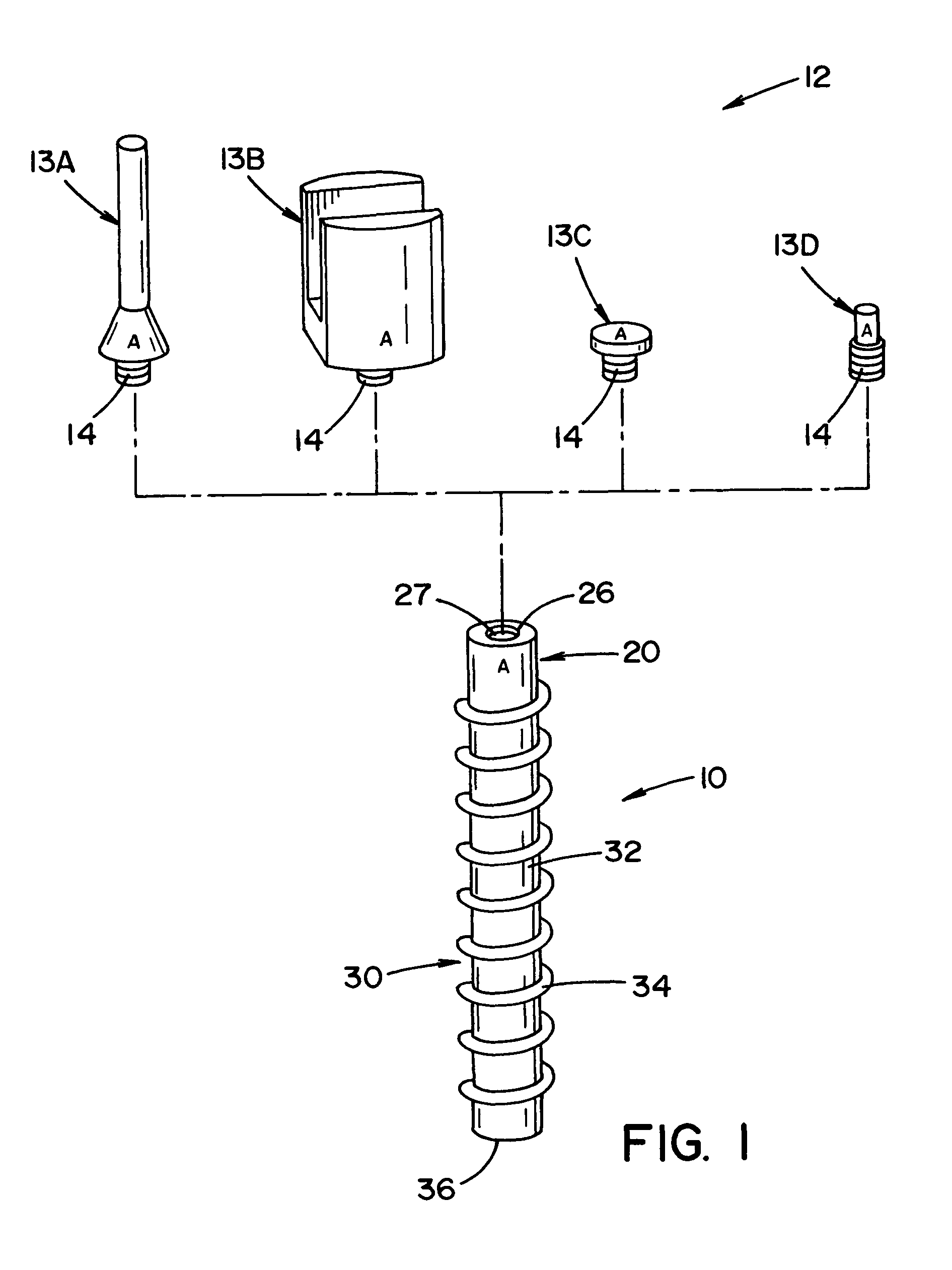
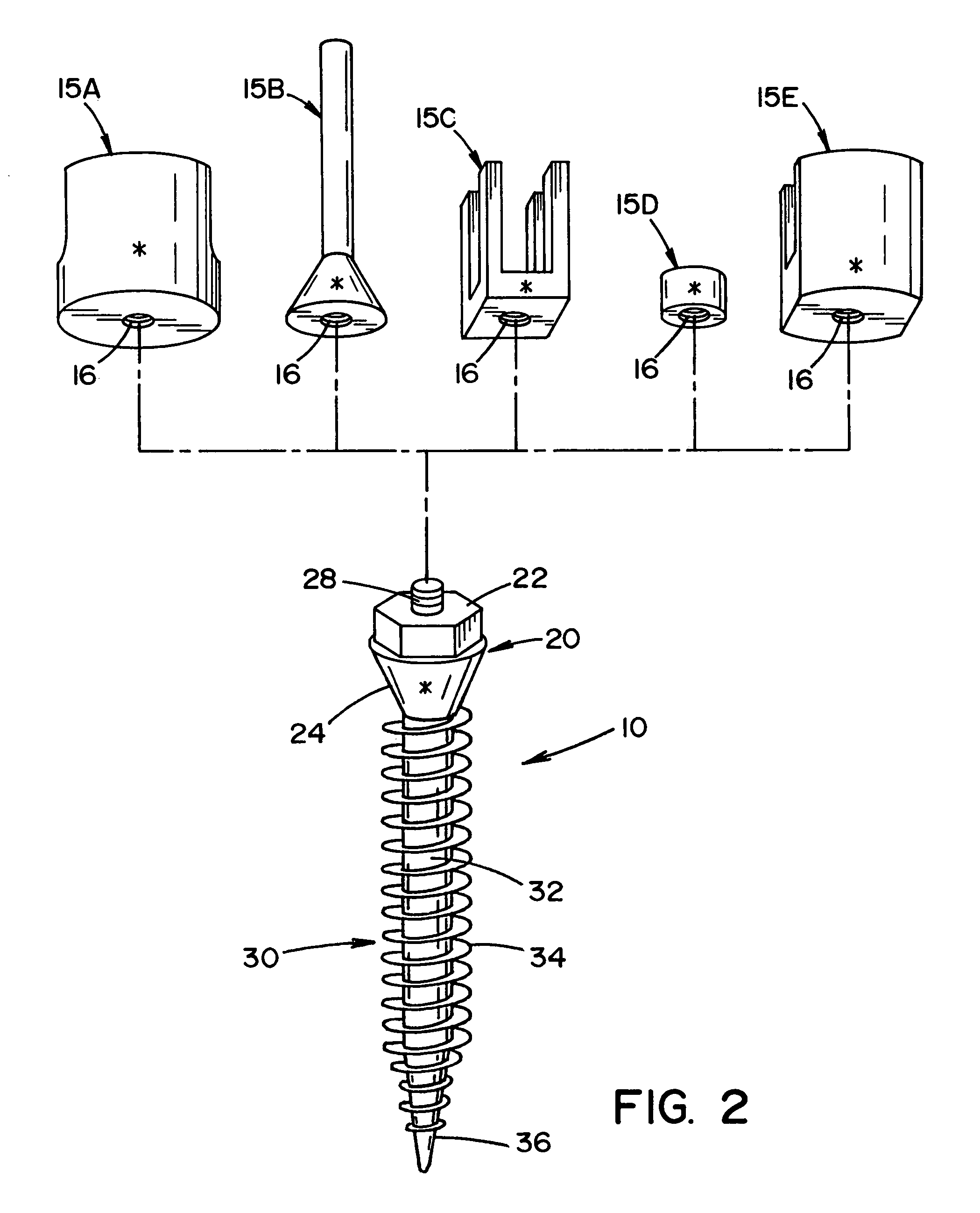
[0068]Referring to the drawings, wherein the showings are for the purpose of illustrating the preferred embodiment of the invention only and not for the purpose of limiting same, FIG. 1 illustrates a novel bone screw system for insertion into bone and / or cartilage of a vertebrae. The bone screw system will be described with particular reference for use with surgical procedure involving the vertebrae and will be thus referred to as a pedicle screw system; however, it will be appreciated that the bone screw system can be used in other regions of a body (e.g., leg, arm, hand, foot, knee, hip, pelvis, rib cage, skull, etc.) to promote healing in such regions. It will also be appreciated that the bone screw system can be used in other areas of the vertebrae such as, but not limited to, the laminna, facets, etc.

[0069]Orthopaedic surgeons, as well as neurosurgeons, have long recognized the need for the use of pedicle screws in the treatment of spinal pathologies, deformities and traumas. T...


PUM


Abstract

A prosthetic screw system that includes a prosthetic screw for at least partial insertion into a bone and / or cartilage. The prosthetic screw includes a head and a lower portion connected to the head. The prosthetic screw system also includes a set of head-pieces that can be connected to the head of the prosthetic screw. The head-pieces have differing configurations that are designed to be connected to different types of components of a prosthetic system. The universal connection arrangement between the prosthetic screw and the set of head-pieces enables the prosthetic screw to be customized for connection with a variety of components of a prosthetic system. The head-pieces can alternatively or additionally include a mechanical and / or electrical mechanism that provides one or more substances (e.g., medicine and / or other biological agent, etc.) and / or electrostimulation to a surgical site.

Description

[0001]The present invention claims priority on U.S. Provisional Patent Application Ser. No. 60 / 502,957 filed Sep. 16, 2003 entitled “Bone Anchor Prosthesis and System”, which is incorporated herein by reference.[0002]The present invention pertains to prosthetic implants, and more particularly to bone screws, nails or posts that can be inserted into bone and / or cartilage, and more particularly to pedicle screws, nails or posts that can be inserted into a vertebra.BACKGROUND OF THE INVENTION[0003]The human spine is made up of a column of thirty-three bones and their adjoining structures. The bodies of these vertebrae are connected by anterior and posterior ligaments and by discs of fibrocartilage generally known as intervertebral discs. These discs are positioned between opposite faces of adjacent vertebral bodies. This column of vertebrae and intervertebral discs forms a central axis that supports the head and torso. These vertebrae also enclose an opening through which the spinal co...

Claims


Application Information

Patent Timeline
Patent Type & Authority Patents(United States)
IPC IPC(8): A61B17/04A61B17/84A61B17/00A61B17/34A61B17/68A61B17/70A61B17/86A61B17/88A61F2/00A61N1/32A61N1/40
CPCA61B17/686A61B17/7061A61B17/8605A61B17/8685A61N1/326A61B17/3472A61B17/7032A61B17/7098A61B17/864A61B2017/00734A61F2310/00389A61N1/40
Inventor BISCUP, ROBERT S.
Owner SPINECO
Learn More