Rotary disk humidifier

a technology of humidifier and disk, which is applied in the direction of lighting and heating apparatus, heating types, separation processes, etc., can solve the problem of grossly insufficient wetted area of the disk to reach the optimal area

Active Publication Date: 2011-11-29
BRAEBURN SYST
View PDF19 Cites 16 Cited by
  • Summary
  • Abstract
  • Description
  • Claims
  • Application Information

AI Technical Summary

Benefits of technology

[0017]Other objects and advantages of the present invention w

Problems solved by technology

At the other theoretical extreme with the water level just at or slightly above the outer diameter of the disks, there is a grossly insufficient wetted area of the disk to approach the optimum area.

Method used


Image

  • Rotary disk humidifier
  • Rotary disk humidifier
  • Rotary disk humidifier

Examples


Embodiment Construction

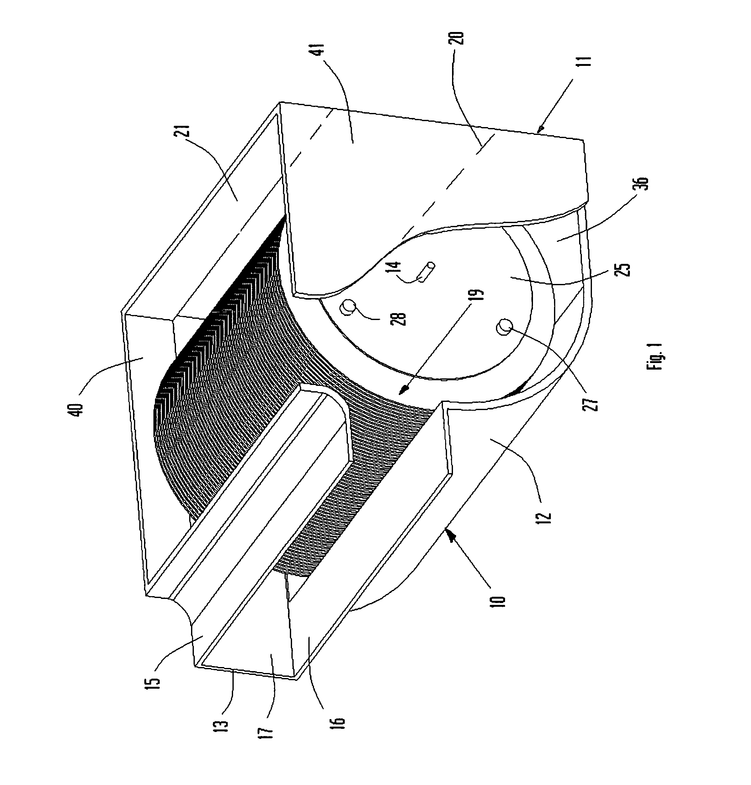
[0024]Viewing FIGS. 1 and 2, a multiple disk humidifier is illustrated generally designated by the reference numeral 10, and is seen to include a housing 11 consisting of an arcuate front panel 12 having an integral inlet 13 that is formed by top panel 15, bottom panel 16, and end panels 17, which direct air flow radially across disk stack 19 and through outlet opening 20 in rear panel 21 illustrated in dotted lines in FIG. 1.

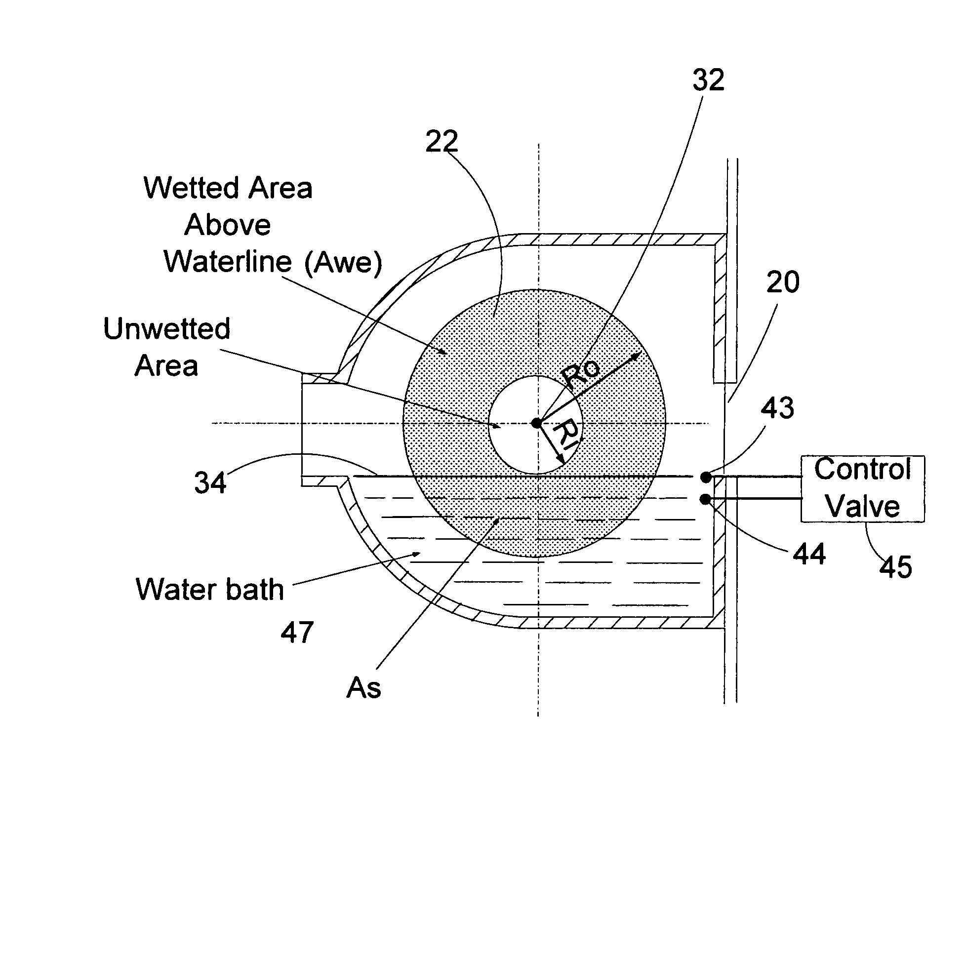
[0025]The disk stack 19 is driven by a motor not illustrated in the drawings and is seen to include a plurality of circular disks 22 closely spaced from one another as illustrated in FIG. 2 in parallel mounted configuration which are held in assembly by end plates 24 and 25 that carry rods 27, 28 and 29 (see both FIGS. 1 and 2) that hold the disks in position. A central shaft 14 keyed through the end plates 24 and 25 drives the disk stack 19 in rotation. As seen in FIG. 3, each of the disks has a radius Ri, which is the distance between center rotation 32 and t...


PUM

PropertyMeasurementUnit
Fractionaaaaaaaaaa
Fractionaaaaaaaaaa
Fractionaaaaaaaaaa

Abstract

A rotary disk humidifier of the type that has multiple parallel spaced disks rotatably mounted in a water reservoir in a housing with controls for maintaining the water level in the housing to obtain an optimum wetted disk area above the water level exposed to air flow to achieve optimum humidification. At one theoretical extreme, the water level is at or above the center of rotation of disks decreasing the area of the disks exposed to free air flow through the housing. At the other theoretical extreme with the water level just at or slightly above the outer diameter of the disks, there is a grossly insufficient wetted area of the disk to approach the optimum area. Between those extremes there is a mathematical optimal range of the ratio inner wetted diameter of the disk Ri to the outside wetted diameter of the disk Ro (or the average outer diameter of the disk—the disk may not be circular) of about 0.30.

Description

BACKGROUND OF THE INVENTION[0001]Rotary disk humidifiers have been commercially available for decades. They generally include a stack of flat circular disks that are mounted closely spaced and parallel to one another on a central shaft that rotates and immersed in a water reservoir so that as the disks rotate through the water bath, air flows across the disks above the water bath entraining water vapor in the air stream and thereby humidifying air exiting from the humidifier.[0002]However, no attempt insofar as the present inventor is aware, has been made to optimize the wetted area of the disks exposed to air flowing through or across the disks.[0003]For example, in the Burns, U.S. Pat. No. 5,795,505, a humidifier is disclosed with a spaced stack of annular disks rotated through a water bath with an axial flow inlet 44 that drives air axially through the center of the disks, which air is blocked by a plate 26 to cause the air to turn radially across the disks. No attempt or discuss...

Claims


Application Information

Patent Timeline
IPC IPC(8): B01D3/04
CPCF24F6/06Y10S261/34
Inventor SODERLUND, ERNEST E.
Owner BRAEBURN SYST
Why Eureka
Try Eureka