
revolver type AUV (Autonomous Underwater Vehicle) rear-mounted stabilizing ring stability augmentation device

The technology of a stabilization device and a stabilization ring is used in transportation and packaging, steering with a rudder, special-purpose ships, etc. It can solve problems such as limited applicability, changes in internal space and shape, and instability in high-speed straight sailing. Achieve the effects of improving viscous fluid dynamics, increasing contact area, and strong anti-interference ability

Inactive Publication Date: 2021-08-06
NORTHWESTERN POLYTECHNICAL UNIV
View PDF9 Cites 2 Cited by
  • Summary
  • Abstract
  • Description
  • Claims
  • Application Information

AI Technical Summary

Problems solved by technology

However, this technical solution cannot be applied to the existing rotary AUV due to the need to install the main and ailerons, and its internal space and shape have undergone major changes.
Secondly, its dual-mode navigation of gliding and high-speed direct flight cannot match most of the existing rotary AUVs that rely on power systems such as propellers, and its applicability is greatly limited.
At the same time, this technical solution is a related solution to the dynamic instability of high-speed direct navigation, and cannot effectively solve the problem of AUV low-speed navigation instability under low-speed or micro-speed conditions below 3kn.

Method used


Image

  • revolver type AUV (Autonomous Underwater Vehicle) rear-mounted stabilizing ring stability augmentation device
  • revolver type AUV (Autonomous Underwater Vehicle) rear-mounted stabilizing ring stability augmentation device
  • revolver type AUV (Autonomous Underwater Vehicle) rear-mounted stabilizing ring stability augmentation device

Examples


Embodiment approach

[0033] Structural principle of the present invention and embodiment are as follows:

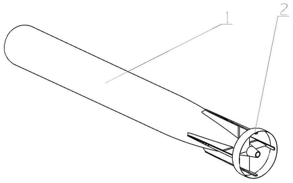
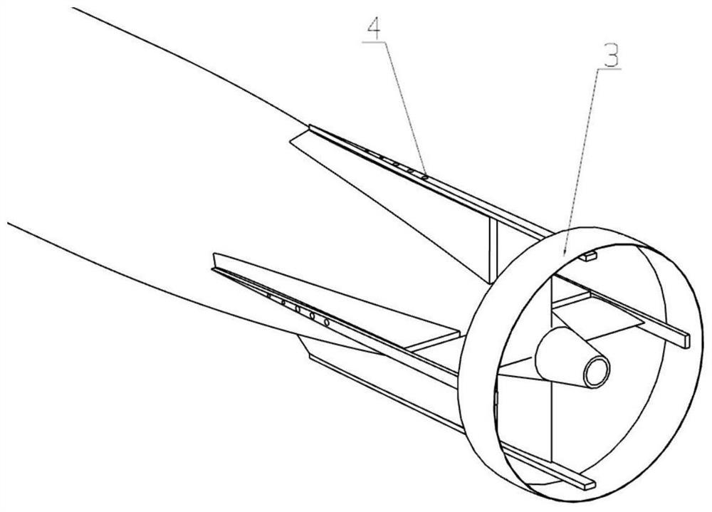
[0034] refer to figure 1 and figure 2 As shown, the present invention is a rear stabilization ring stabilization device based on a rotary AUV. The rotary AUV includes a cross-shaped fin rudder and a rear stabilization ring mechanism 2, and the rear stabilization ring mechanism 2 includes a stabilization ring piece 3 and fixed pole 4. The stabilizing ring piece 3 is a circular ring structure, its radial section is an airfoil section, and the leading edge faces the main body of the AUV; the fixing rod 4 is a conical sheet structure; the four fixing rods 4 are arranged symmetrically, and one end is respectively fixed on the AUV cross The other ends of the outer edges of the four fin plates of the fin rudder are respectively fixed at symmetrical positions on the inner peripheral surface of the stabilizing ring 3 .

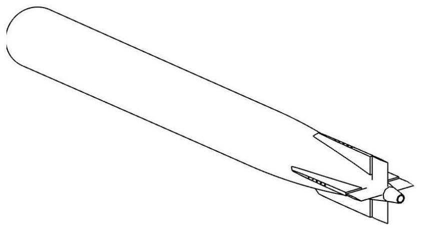
[0035] image 3 is the vehicle shape of AUV, Figure 4 For the detailed dra...


PUM

PropertyMeasurementUnit
Thicknessaaaaaaaaaa

Abstract

The invention discloses a revolver type AUV (Autonomous Underwater Vehicle) rear-mounted stabilizing ring stability augmentation device, and belongs to the field of hydromechanics and underwater vehicle maneuverability and stability. The device comprises a stability augmentation ring piece and a fixing rod. The stability augmentation ring piece is of a circular ring structure, the radial section of the stability augmentation ring piece is a wing-shaped section, and the front edge faces the AUV body. The fixing rod is of a strip-shaped sheet structure. The four fixing rods are evenly distributed in the circumferential direction, one ends of the four fixing rods are fixed to the outer edges of four fin plates of the AUV cross fin rudder respectively, and the other ends of the four fixing rods are fixed to the inner circumferential face of the stability augmentation ring piece respectively. On one hand, the stability augmentation ring sheet 2 increases the control force and the control torque of the aircraft in a micro-speed state by increasing the wetted area of the aircraft, and on the other hand, the stability augmentation ring sheet 2 can rectify water flow flowing through the cross rudder and reduce the influence of incoming flow on wake flow of the aircraft. The beam effect is achieved on the wake flow of the underwater vehicle, and the influence of the wake flow on the stability of the vehicle is effectively reduced. The AUV can better adapt to the requirements of different working conditions on high maneuverability and high stability.

Description

technical field [0001] The invention belongs to the fields of hydrodynamics, maneuverability and stability of underwater vehicles, and in particular relates to a rear-mounted stabilization ring stabilization device for a rotary body type AUV. Background technique [0002] The stability surface and control surface of the rotary underwater vehicle determine its kinematic performance, and are usually arranged at the tail. As far as the heeling motion of the vehicle is concerned, the empennage can generate both control moment and recovery moment, as well as disturbance moment. Due to the emergence of environmental detection, information collection and precise manipulation tasks, higher requirements are put forward for AUV's underwater navigation stability. For example: when the underwater vehicle is performing underwater recovery work, the AUV is required to have low-speed navigation stability, so that the AUV can maintain a good attitude during the low-speed docking process to...

Claims


Application Information

Patent Timeline
IPC IPC(8): B63C11/52B63G8/14B63H25/38
CPCB63C11/52B63G8/14B63H25/38
Inventor 杜晓旭刘鑫王鹏潘光宋保维
Owner NORTHWESTERN POLYTECHNICAL UNIV
Learn More