
Hollow structural members, a rail system and methods of manufacturing

a technology of structural members and rail systems, applied in the direction of girders, rope railways, ways, etc., can solve the problems of rack railway systems suffering from derailments, systems are inherently complex mechanical systems, and conventional rail transportation systems may not be suitable for us

Active Publication Date: 2011-11-29
HILLTRAC
View PDF62 Cites 42 Cited by
  • Summary
  • Abstract
  • Description
  • Claims
  • Application Information

AI Technical Summary

Benefits of technology

"The patent text describes a method for creating a hollow triangular prism-shaped structural member and a rail system using these structural members. The technical effects of this invention include improved load-bearing capacity, reduced weight, and improved thermal stability. The hollow triangular prism-shaped structural member has a unique cross-section that increases its strength and stability, and the rail system utilizing these structural members has been designed to withstand high levels of stress and thermal expansion."

Problems solved by technology

Such conventional rail transportation systems may not be suitable for use on steep grades where traction may become a problem.
However, these systems are inherently complex mechanical systems.
However, such rack railway systems suffered from derailments when the cog wheel slipped out of the teeth in the rail rack.
Additionally, the rail rack itself was expensive to produce and maintain.
Furthermore, switches for rack railways were more complex because of the rail rack.
While these cable and chain-driven systems tend to be simpler than the friction-based systems for inclined applications, they do not lend themselves well to applications that include turns and changes in inclination because of the nature of cable and chain-driven drives.
More specifically, it is difficult to configure a chain or cable for driving a car over a track having turns and changes in inclination because the force exerted by a chain or cable is linear in nature.
Thermal expansion of steel and other track materials has been a limiting factor for simple track design for many years.
If such expansion is not accounted for through stronger reinforcements and supports, the result can be bowing or buckling of the track due to thermal expansion.
This thermal expansion results in a deflection of the track between the captured points.
This deflection may cause the track to bend, twist, or at worst case, buckle the track or supports, all of which are undesirable.
The deflection also causes additional stresses to all connections including fasteners and connection brackets and / or weldment points requiring the strengthening of these connections.
Over time with the increase in thermal cycles, the potential for premature failure of these connection or weldment locations generally increases, resulting in an undesirable failure.
The design, manufacturing and installation costs for both labor and materials to compensate for this thermal expansion all increase as a result.
For these reasons, the reinforcement method is not preferred as it creates considerable design challenges and increases the economic cost to the system.
A low-friction clamping system is susceptible to contamination and requires additional maintenance to ensure free movement in the track system.
This method, while achieving a desired result for reducing the stresses in a long track system, is complicated and requires significant maintenance for long-term operation.
For these reasons, the low-friction clamping system approach is not preferred because of the additional maintenance and expense to operate such an intricate system.

Method used


Image

  • Hollow structural members, a rail system and methods of manufacturing
  • Hollow structural members, a rail system and methods of manufacturing
  • Hollow structural members, a rail system and methods of manufacturing

Examples


Embodiment Construction

[0046]Reference will now be made to figures of embodiments of the present invention wherein like structures will be provided with like reference designations. It is understood that the drawings are diagrammatic and schematic representations of exemplary embodiments of the present invention and are neither limiting of the present invention nor are they necessarily drawn or shown to scale.

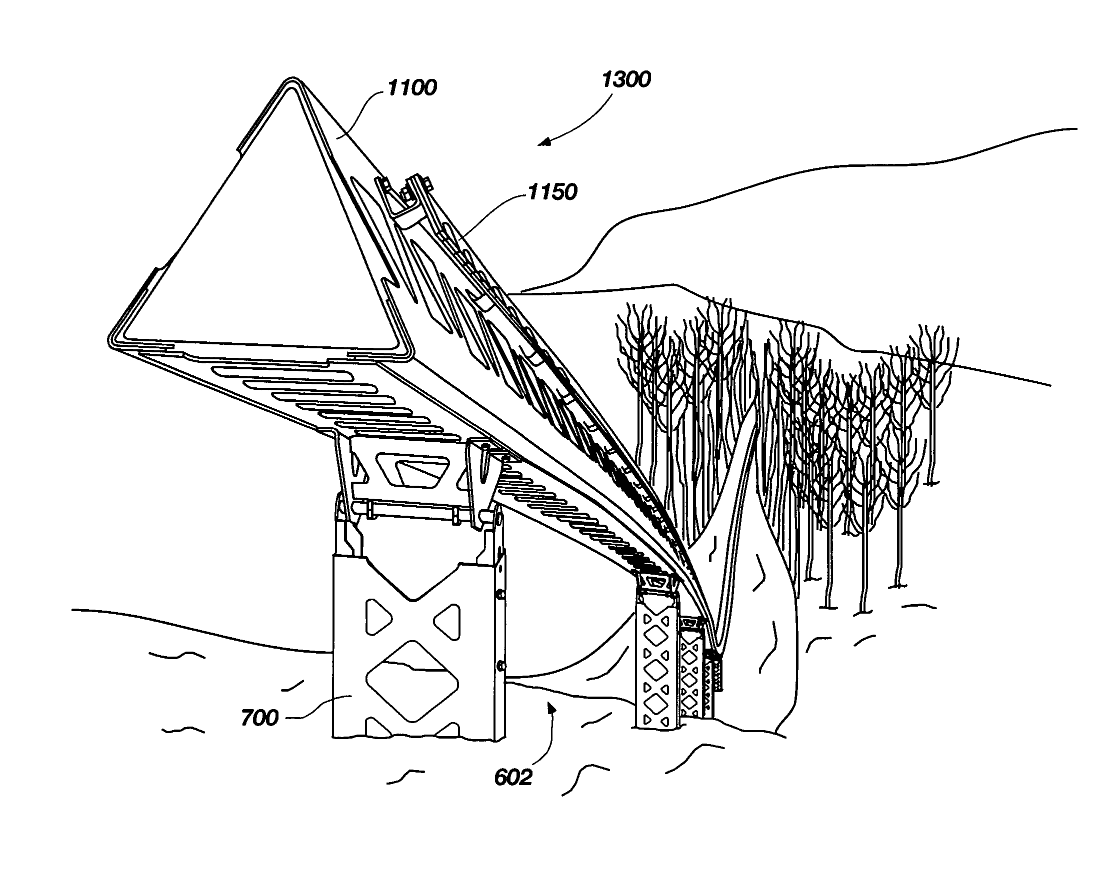
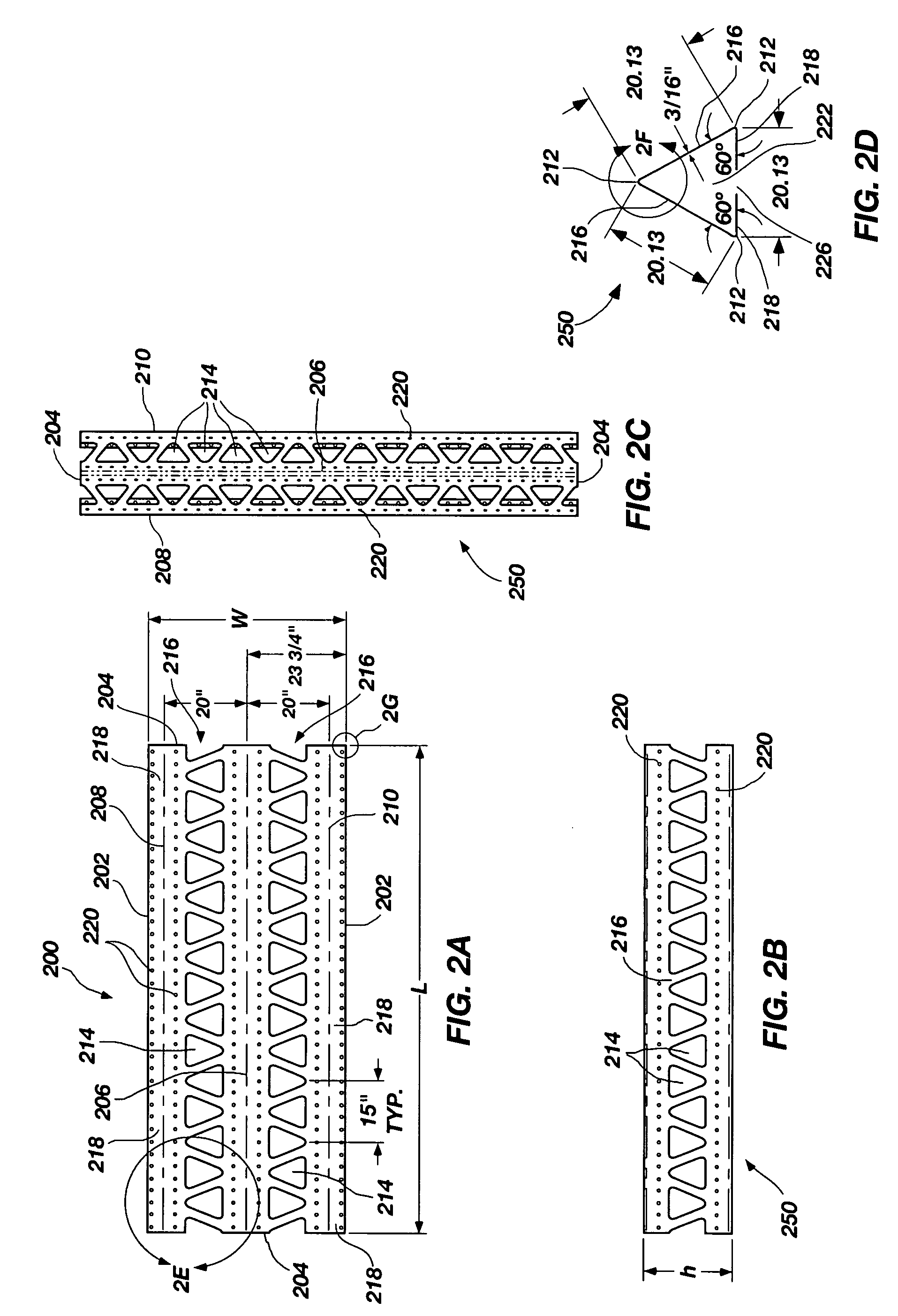
[0047]Embodiments of the present invention are directed to a novel hollow triangular prism-shaped structural member and methods of forming same. This triangular cross-sectioned member is particularly useful as an assembly that may form a track upon which a car may ride. However, it will be evident that there are many other applications for such a light weight structural member, for example a radio tower.

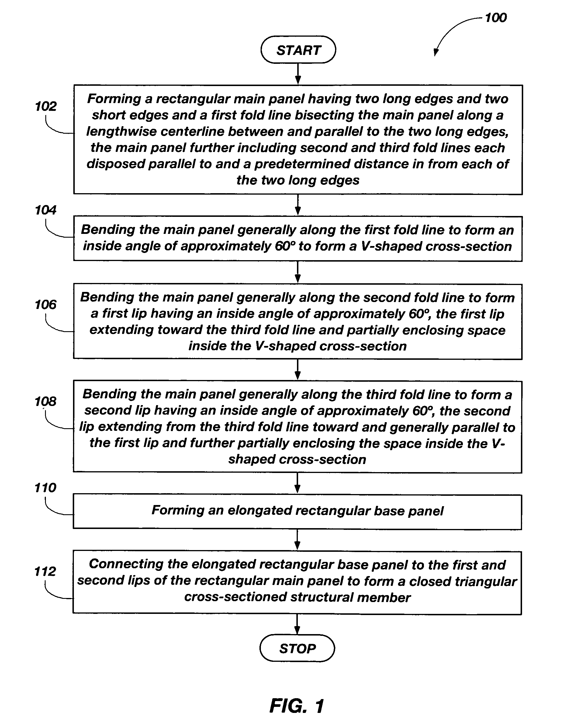
[0048]FIG. 1 is a flowchart of an embodiment of a method 100 of forming a hollow triangular prism-shaped structural member, according to the present invention. Method 100 may include forming 102 a rec...


PUM

PropertyMeasurementUnit
temperatureaaaaaaaaaa
inside angleaaaaaaaaaa
angleaaaaaaaaaa

Abstract

The invention is hollow structural members, a rail system based thereon and method of manufacturing such hollow structural members. Embodiments of the structural members may be hollow triangular prism-shaped with a cross-section that is triangular, isosceles, hexagonal or otherwise. Embodiments of rail systems based on hollow structural members are also disclosed. Embodiments of the rail systems disclosed herein may also include reaction assemblies for local dissipation of stresses due to thermal expansion of track materials.

Description

BACKGROUND OF THE INVENTION[0001]1. Field of the Invention[0002]This invention relates generally to structural members particularly useful for railed transportation systems. More particularly, the invention relates to a hollow structural members, a rail system based thereon and methods of manufacturing such hollow structural members.[0003]2. Description of Related Art[0004]Railed transportation systems are well known in the art. Most conventional railways for transportation of people, goods and other resources rely on friction between the drive wheels and rails. Such conventional rail transportation systems may not be suitable for use on steep grades where traction may become a problem. To compensate for the lack of necessary friction, various elaborate multiple-wheeled and spring-loaded friction-based rail transportation systems have been devised, such as those described in U.S. Pat. No. 4,602,567 to Hedström, U.S. Pat. No. 5,069,141 to Ohara et al., U.S. Pat. No. 5,231,933 to DiRo...

Claims


Application Information

Patent Timeline
Patent Type & Authority Patents(United States)
IPC IPC(8): E01B1/00
CPCE01B25/08E01B25/10B23P15/20E01B5/02E04C3/08B61B5/00Y10T29/49616
Inventor HEPNER, ALANMETIVIER, DAVID
Owner HILLTRAC
Learn More