
Electromagnetic field intensity calculating method and apparatus

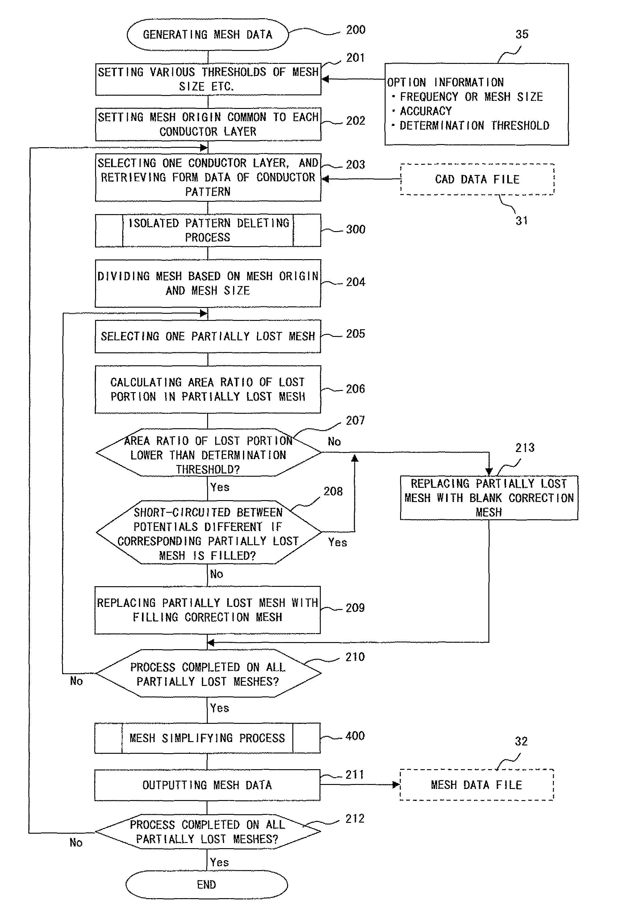
a technology of electromagnetic field intensity and calculation method, which is applied in the direction of electric/magnetic computing, analogue processes for specific applications, instruments, etc., can solve the problems of degradation of analysis precision, increasing the number of steps required for the entire designing step, and boundary mismatch of mesh data between layers, etc., to achieve correct and efficient generating of mesh data

Inactive Publication Date: 2011-11-22
FUJITSU LTD
View PDF13 Cites 5 Cited by
  • Summary
  • Abstract
  • Description
  • Claims
  • Application Information

AI Technical Summary

Benefits of technology

[0020]The present invention aims at providing a technique of correctly and efficiently generating mesh data provided for a simulation analysis of electromagnetic field intensity in the moment method using the CAD data in the computer-aided designing step as is.
[0021]The present invention also aims at providing a technique of shortening the time required to perform a developing step of electronic equipment etc. including the simulation analyzing step of electromagnetic field intensity.
[0022]The present invention further aims at providing a technique of speeding up the analysis by reducing the number of mesh patterns included in the mesh data provided for the simulation analysis of the electromagnetic field intensity in the moment method and improving the precision of analysis by microscopic mesh patterns.

Problems solved by technology

Although the above-mentioned conventional technique has the function of automatically dividing the flat conductor pattern of the power supply layer and the ground layer obtained from the CAD data into mesh form, the flat conductor pattern is divided as is into mesh form, and therefore squares and triangles are mixed in an obtained mesh pattern, which is not appropriate for the moment method.
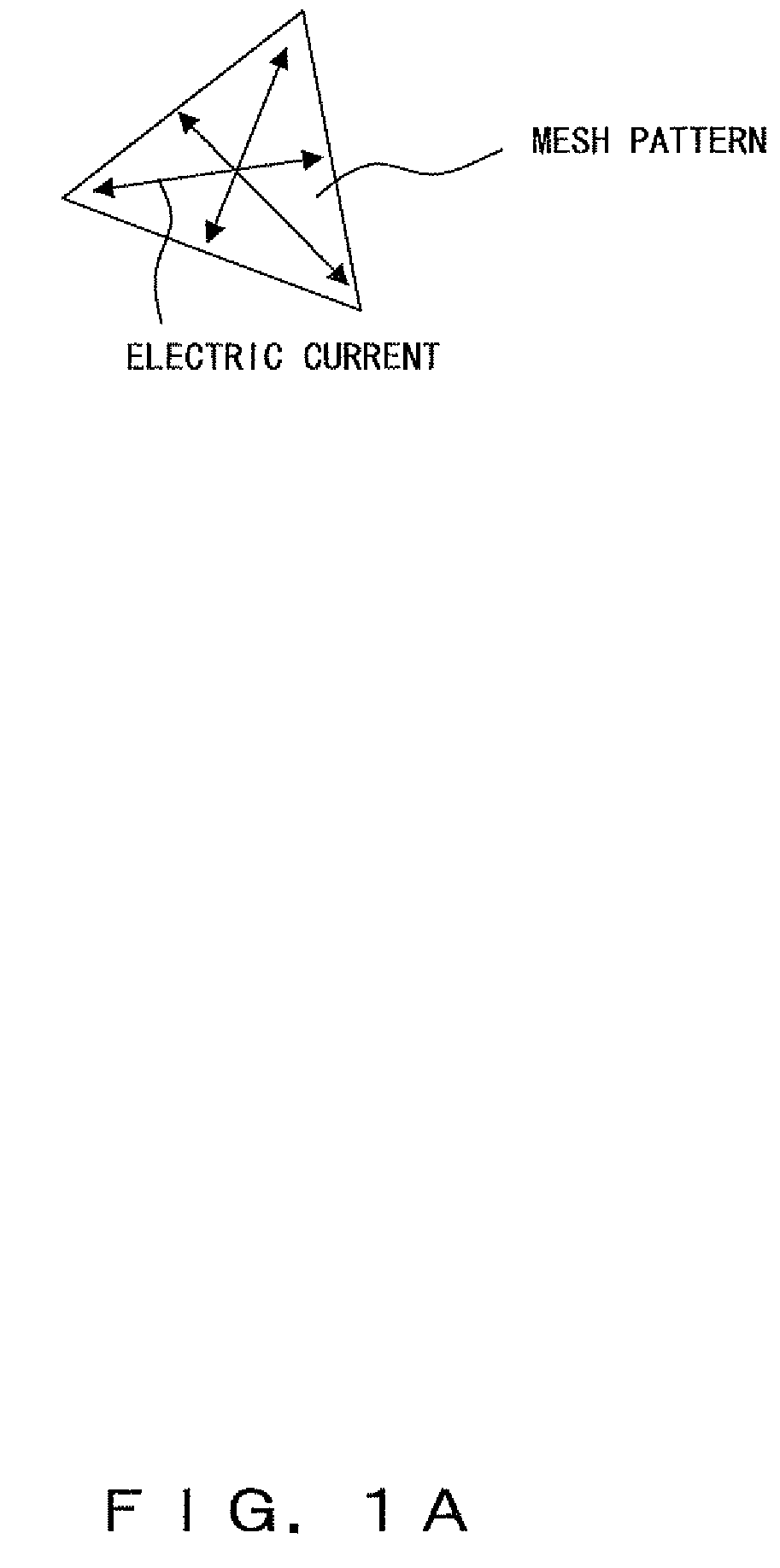
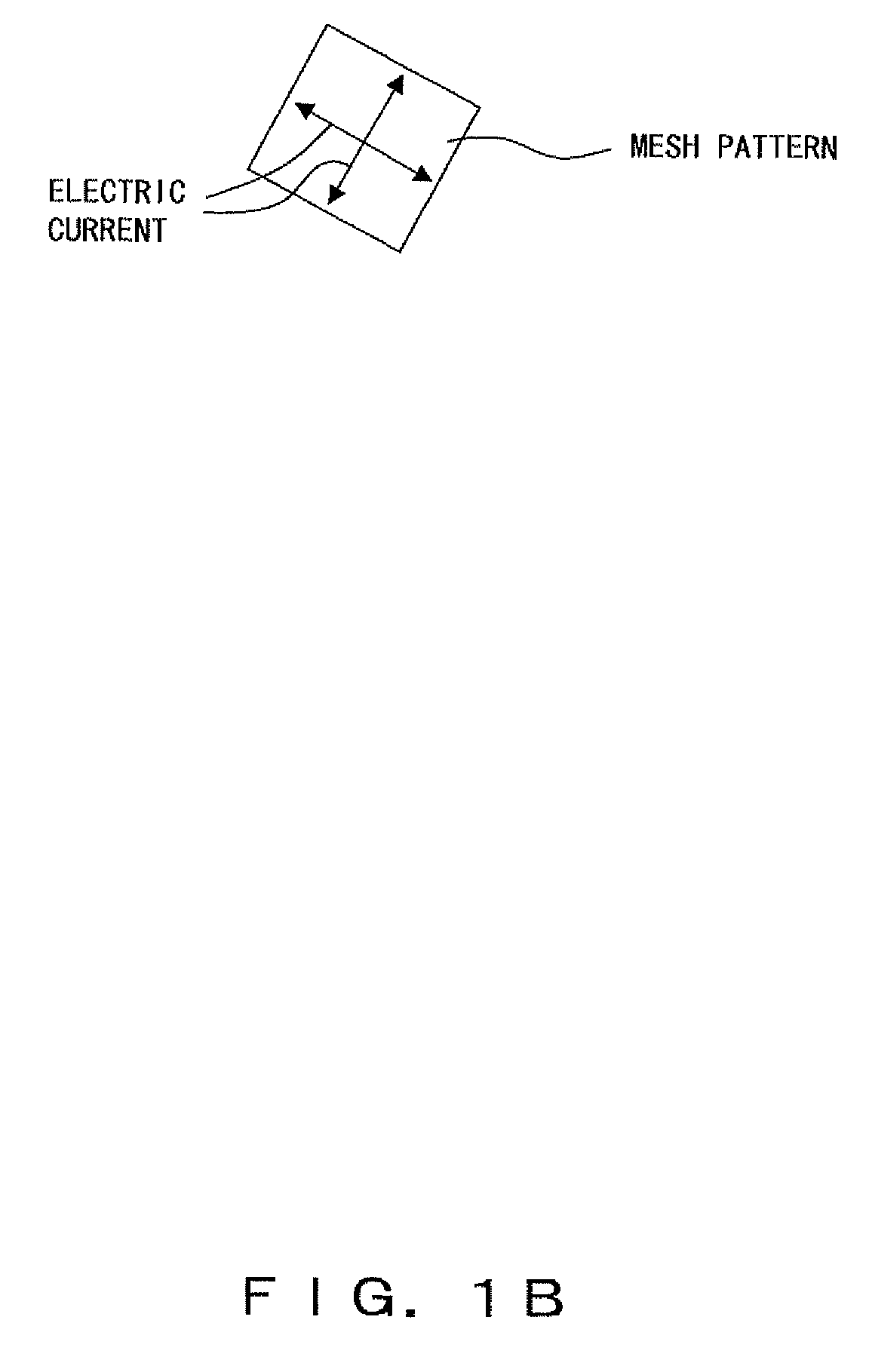
Therefore, for example, in a mesh pattern formed by a plurality of triangles and a mesh pattern formed by triangles and squares in a mixed manner as shown in FIG. 1C, the current passes unevenly, and delayed propagation occurs, thereby causing the degradation in precision of analysis.
However, in this case, it is necessary in the step of the CAD apparatus to separately regenerate the CAD data for an electromagnetic wave analysis in addition to the original CAD data, thereby causing another problem of increasing the number of steps required for the entire designing steps.
Therefore, the boundary mismatch of mesh data between the layers can be a factor of the degradation of precision of analysis.

Method used


Image

  • Electromagnetic field intensity calculating method and apparatus
  • Electromagnetic field intensity calculating method and apparatus
  • Electromagnetic field intensity calculating method and apparatus

Examples


Embodiment Construction

[0074]The modes for embodying the present invention are described below in detail by referring to the attached drawings.

[0075]FIG. 3 shows the concept of an example of the configuration of the electromagnetic field intensity calculation apparatus for embodying the electromagnetic field intensity calculating method as a mode for embodying the present invention. FIG. 4 is a block diagram showing an example of the configuration of the information processing system realizing the electromagnetic field intensity calculation apparatus according to a mode for embodying the present invention.

[0076]FIG. 5 is a flowchart showing an example of the step of manufacturing electronic equipment such as a printed circuit board etc. when the electromagnetic field intensity calculating method and apparatus according to a mode for embodying the present invention is used. FIGS. 6, 7, and 8 are flowcharts showing examples of the operations of the electromagnetic field intensity calculating method and appa...


PUM


Abstract

There is provided an electromagnetic field intensity calculator for calculating the intensity of electromagnetic field radiated from an electric circuit device based on a moment method. A conductor pattern obtained from CAD data is divided into a square mesh pattern. In the mesh pattern of the outline part, the entire region in the mesh pattern is filled with the conductor pattern according to the ratio of area between the conductor pattern region and the blank region, or subjected to correction for blanking, so that a mesh data model is automatically configured by mesh pattern group consisting of only squares conforming to the moment method and reflecting the outline of the conductor pattern.

Description

CROSS REFERENCE TO RELATED APPLICATION[0001]This application is a continuation of PCT application No. PCT / JP2005 / 005783 (filed 28 Mar. 2005), the content of which is incorporated herein by reference.BACKGROUND OF THE INVENTION[0002]1. Field of the Invention[0003]The present invention relates to an electromagnetic field intensity calculating method, an electromagnetic field intensity calculation apparatus, and a computer readable medium storing a control program, and more specifically to an effective technique applied to an electromagnetic wave analysis technique etc. for calculating the intensity of the electromagnetic field radiated from an electric circuit device such as electronic equipment, a circuit board, etc. on the basis of a moment method.[0004]2. Description of the Related Art[0005]For example, it is known that the moment method disclosed by the patent documents 1, 2, 3, etc. is used as a method for simulating and analyzing an electromagnetic wave radiated from electronic ...

Claims


Application Information

Patent Timeline
Patent Type & Authority Patents(United States)
IPC IPC(8): G06F19/00G06F17/50
CPCG06F17/5036G06F30/367
Inventor NISHINO, SHUKONAGASE, KENJI
Owner FUJITSU LTD
Learn More