
Multi-layer cards with aesthetic features and related methods of manufacturing

a multi-layer card and aesthetic technology, applied in the field of multi-layer cards, can solve the problems of wasting expensive components, unable to copy images successfully, and the known methods of manufacturing laminated cards with metal layers, such as split core process and solid core process, can achieve the effect of minimizing the number of layers, avoiding waste of resources, and easy incorporation

Active Publication Date: 2011-11-22
IDEMIA FRANCE
View PDF14 Cites 15 Cited by
  • Summary
  • Abstract
  • Description
  • Claims
  • Application Information

AI Technical Summary

Benefits of technology

[0013]It is another object of the present invention to provide a method of manufacturing a multi-layer card with aesthetic and / or functional features that achieves a balanced card construction while minimizing the number of layers formed from relatively expensive materials.
[0014]It is yet another object of the present invention to provide a method of manufacturing a multi-layer card having a metal layer that is easily incorporated into the card structure during the lamination process with minimal expenditure of resources and reduced possibility of waste.
[0015]It is still another object of the present invention to provide a method of manufacturing a multi-layer card with aesthetic and / or functional features that avoids creating an image on the expensive components of the card structure, such as, for example, a metal layer.
[0016]It is a further object of the present invention to provide a method of manufacturing a multi-layer card that may have aesthetic and / or functional features visible from both sides thereof while avoiding undesirable capacitor effects in the laminated structure.

Problems solved by technology

Furthermore, driven by the ever growing need for secure financial transactions, as well as more complex operations—combining, for example, payment and secure network access—conventional magnetic stripe cards are increasingly being phased out and replaced by so-called “smart cards,” i.e. laminated cards incorporating an integrated circuit or chip.
Often, in addition to providing a banking card, access card, identification card, and the like with a magnetic stripe and / or chip for security purposes, as an additional security feature to hinder counterfeiters, such cards are also provided with a holographic image because such images are difficult to copy successfully.
Known methods for manufacturing laminated cards having metal layers, such as, for example, split core process and the solid core process, suffer from several drawbacks.
For example, as further explained below, these methods may result in a waste of expensive components and often require special safety precautions to address hazardous conditions inherent therein.
In both of these methods, costs of the materials can be rather substantial, and as a result, such cards are typically several times more expensive to manufacture than conventional cards.
Using more rigid and less expensive materials, such as polyvinylchloride (“PVC”) instead of the material of the backing layer of the foil sheet may reduce the materials cost, but also increases the probability of warping and resulting waste.
Furthermore, in the methods described above, imaging, i.e., creating graphic images and / or alpha-numerical symbols, is carried out on relatively expensive materials, i.e., the metal layer of the foil sheet having an additional image receptive coating thereon and / or the backing layer of the foil sheet, e.g. PET.
Imaging on expensive materials is undesirable given the substantial amount of waste typically involved in the imaging process.
Also, certain aspects of known methods for manufacturing laminated cards with metal layers may be hazardous and require proper precautions.
For example, if a solvent silkscreen press is used to create images on the foil sheets, there is substantial risk of curling stock in the hot air dryer, which may result in equipment jams, and worse yet, fires caused by the backup of the foil sheets in the dryer.
Potential electrostatic discharge from these cards may damage the processing equipment

Method used


Image

  • Multi-layer cards with aesthetic features and related methods of manufacturing
  • Multi-layer cards with aesthetic features and related methods of manufacturing
  • Multi-layer cards with aesthetic features and related methods of manufacturing

Examples


Embodiment Construction

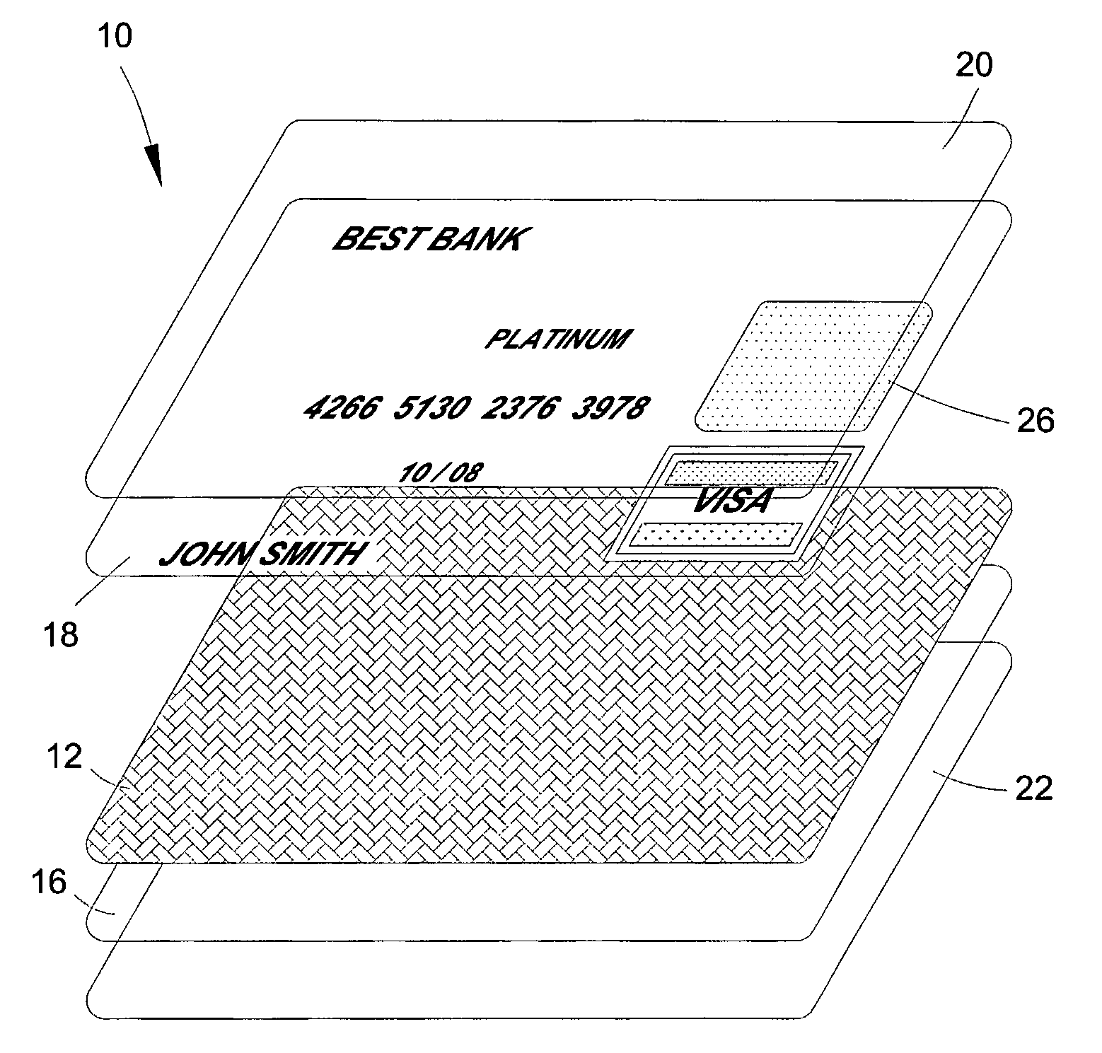
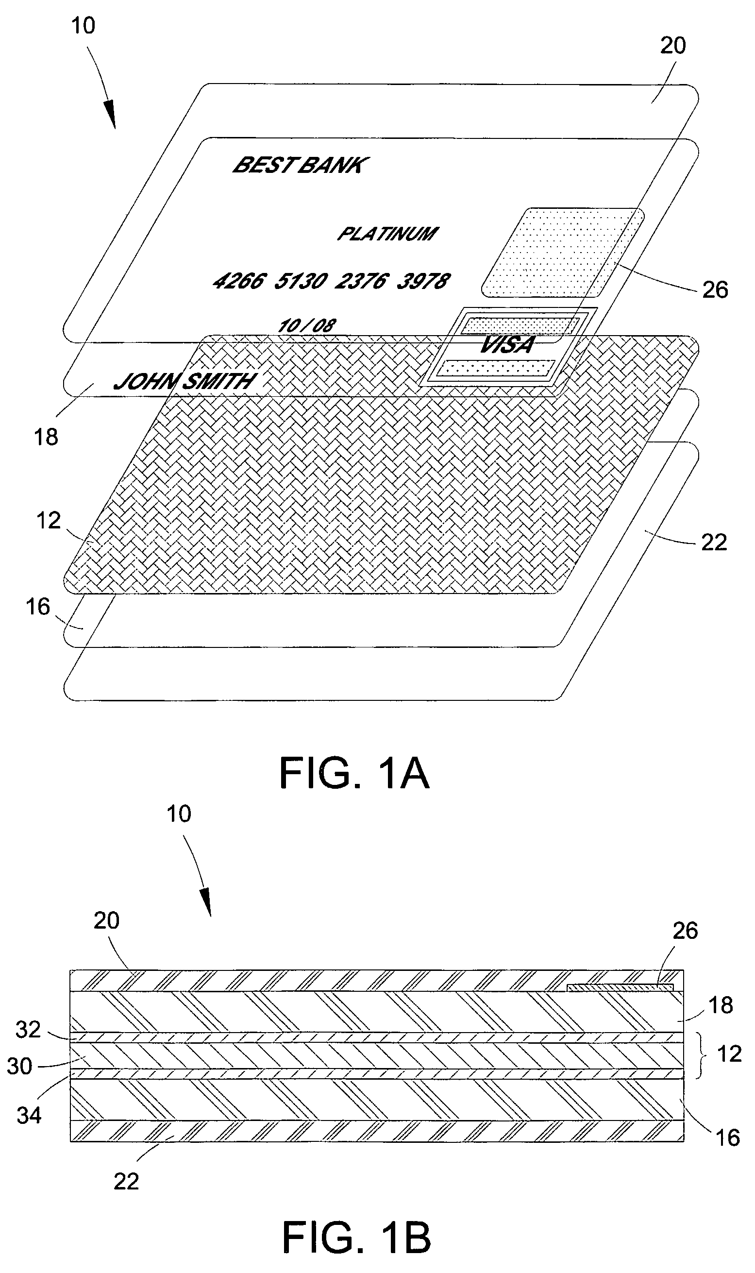
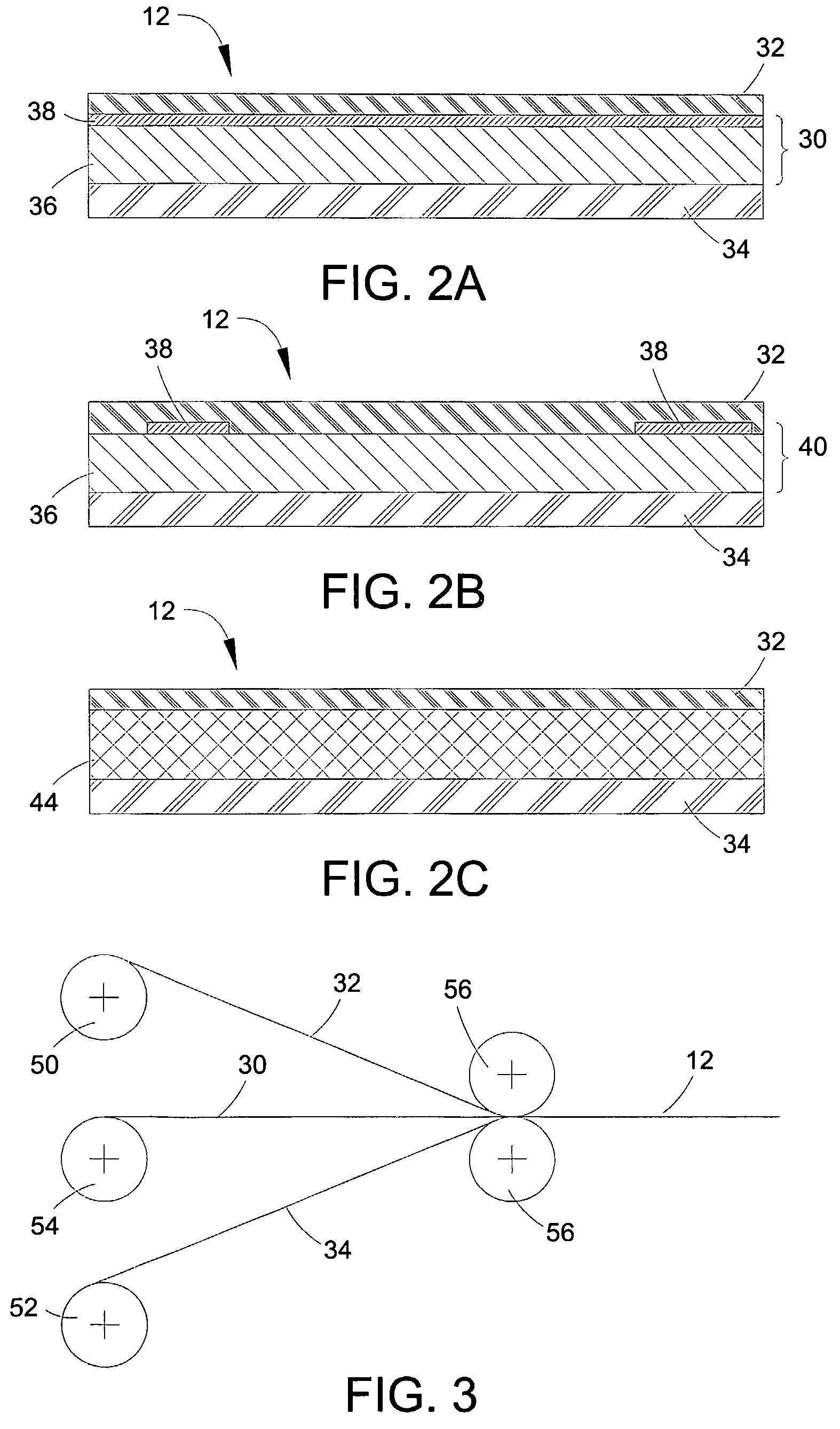
[0031]A key aspect of the present invention involves the manufacturing of multi-layer cards with aesthetic and / or functional features, for example, banking, access, or identification cards, that include a bearing layer formed by an effects layer disposed directly between two core layers. Among other potential benefits, various embodiments of the invention lead to reducing overall manufacturing costs, as compared to methods known in the art, by (i) facilitating a balanced card construction while minimizing the number of layers formed from relatively expensive materials, and (ii) avoiding direct imaging of the effects layer and minimizing waste associated therewith. In addition, enclosing the effects layer between two core layers simplifies further processing of the card and facilitates reliable incorporation of the effects layer into the multi-layered structure with minimal expenditure of resources and reduced possibility of waste.

[0032]Throughout the description, where compositions ...


PUM


Abstract

Multi-layer cards with aesthetic and / or functional features, e.g. banking, access, or identification cards, having a bearing layer that includes an effects layer disposed directly between two core layers are disclosed herein. Among other potential benefits, the layered structure of the bearing layer reduces overall manufacturing costs, as compared to methods known in the art, by facilitating a balanced card construction while minimizing the number of layers formed from relatively expensive materials, avoiding direct imaging of the effects layer and minimizing waste associated therewith, as well as providing for reliable incorporation of the effects layer into the multi-layered structure with minimal expenditure of resources and reduced possibility of waste.

Description

CROSS-REFERENCE TO RELATED APPLICATION[0001]This application is the national phase of International (PCT) Patent Application Serial No. PCT / US2004 / 025611, filed on Aug. 9, 2004, the disclosure of which is incorporated by reference herein.FIELD OF THE INVENTION[0002]The present invention relates generally to multi-layer cards and, more specifically, to laminated banking, access, or identification cards having aesthetic and / or functional features embedded therein.BACKGROUND OF THE INVENTION[0003]The use of secure cards, for example, for processing of financial transactions, enabling secure network access, providing fast and reliable verification of a bearer's identity, and other purposes has become widespread. One example of such secure card is a card with a magnetic strip having a issuer-identifying code, user-identifying code, cipher data and the like, recorded thereon and readable by automated means. Furthermore, driven by the ever growing need for secure financial transactions, as...

Claims


Application Information

Patent Timeline
Patent Type & Authority Patents(United States)
IPC IPC(8): G06K19/02
CPCB42D25/00B42D2033/10B42D25/23B42D25/47B42D25/351
Inventor MOSTELLER, BARRY
Owner IDEMIA FRANCE
Learn More