
Thermally sprayed protective coating for industrial and engineered fabrics

a technology of industrial and engineered fabrics and protective coatings, applied in the direction of presses, weaving, instruments, etc., can solve the problems of thermal degradation, limiting the useful life wear of fabrics and belts, so as to improve functional characteristics

Active Publication Date: 2011-11-15
ALBANY INT CORP
View PDF27 Cites 9 Cited by
  • Summary
  • Abstract
  • Description
  • Claims
  • Application Information

AI Technical Summary

Benefits of technology

The present invention provides a fabric or belt with improved functional characteristics and an efficient and cost-effective method of modifying such fabric or belt. The fabric or belt includes a base support structure and at least one coating or layer applied by a thermal spray process over the support structure or at discrete locations thereof or depositing discrete particles thereon. The use of thermal spray processes such as flame spray, electric wire arc spray, plasma spray, detonation gun deposition, cold spray, or high velocity oxygen fuel combustion spray process for application of the coating to the base support structure or on to another layer, e.g., a resin layer, on the fabric or belt, is also described.

Problems solved by technology

In processes associated with the production of paper, these fabrics and belts can wear and in the case of dryer fabrics and calender belts especially, suffer from thermal degradation.
These temperatures cause the calender belt surface resin to degrade over time, leading to extensive boundary cracking and potential delamination, limiting its useful life.
But when the hardness of the resin is too low, plastic deformation may occur and the life of the belt may be shortened through use.
On the other hand, where the hardness of the resin is too great, other problems can be found such as inflexibility, and a shortened belt lifespan due to cracking of the hardened resin.
The support fabric for all these processes are exposed to some degree of frictional abrasion.
Also the belts and fabrics may partially fill with contaminants.
Surface contamination, particularly with starch, is also a problem.

Method used


Image

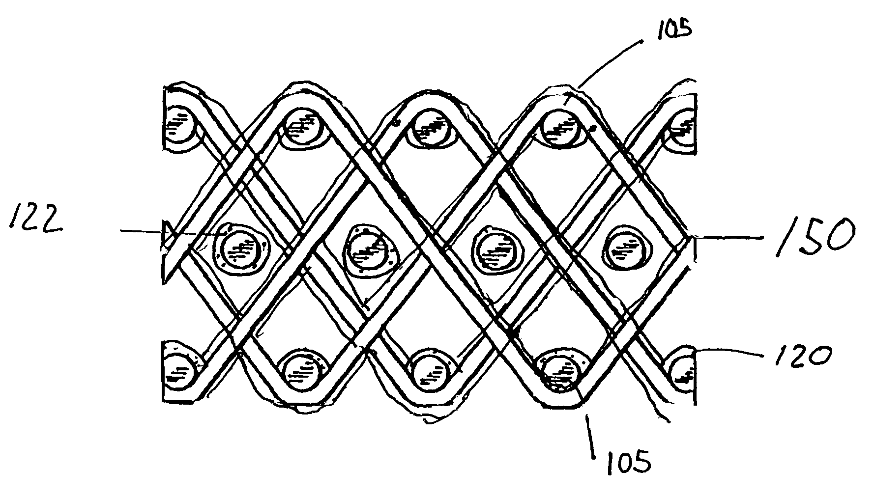
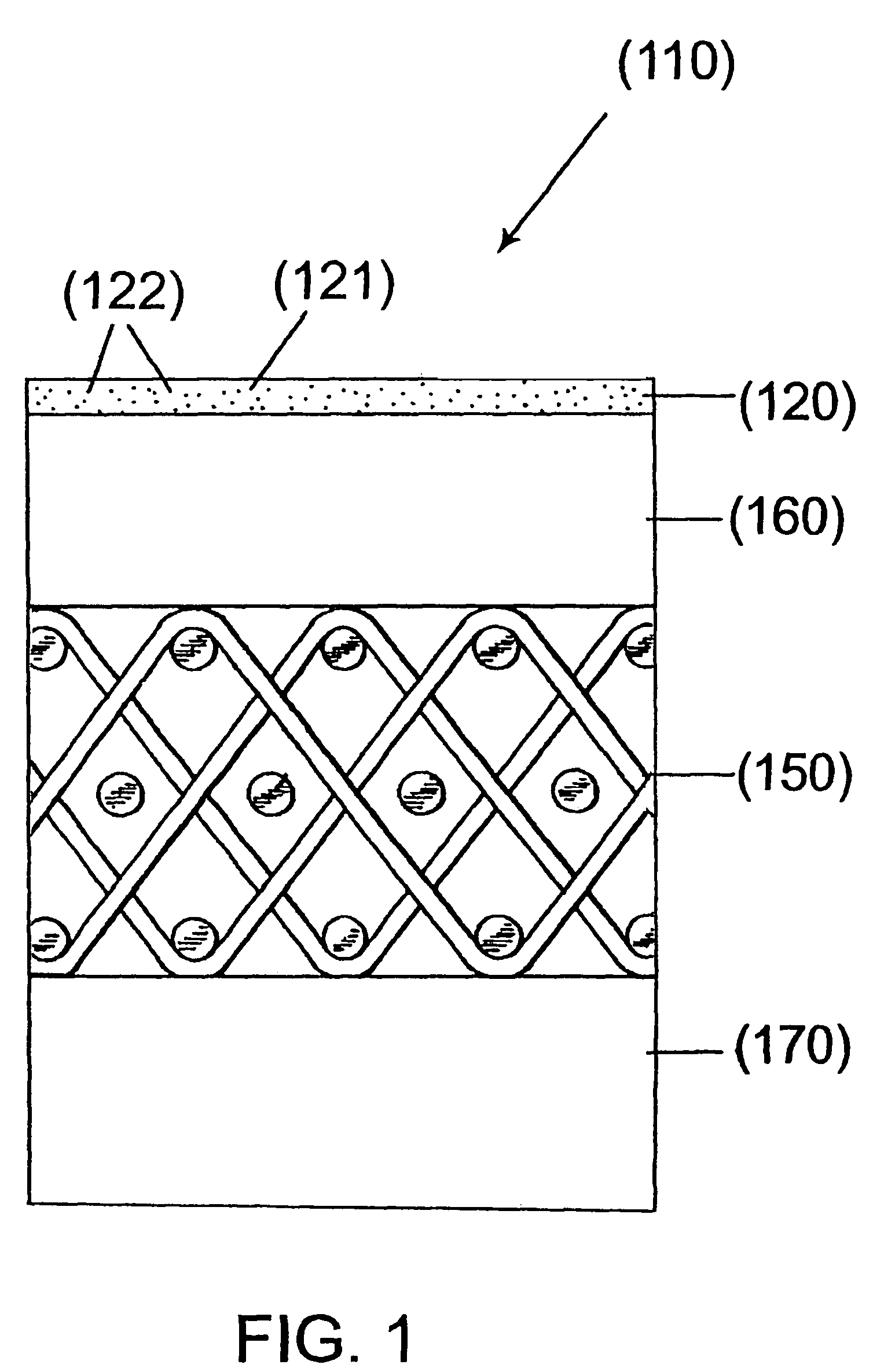
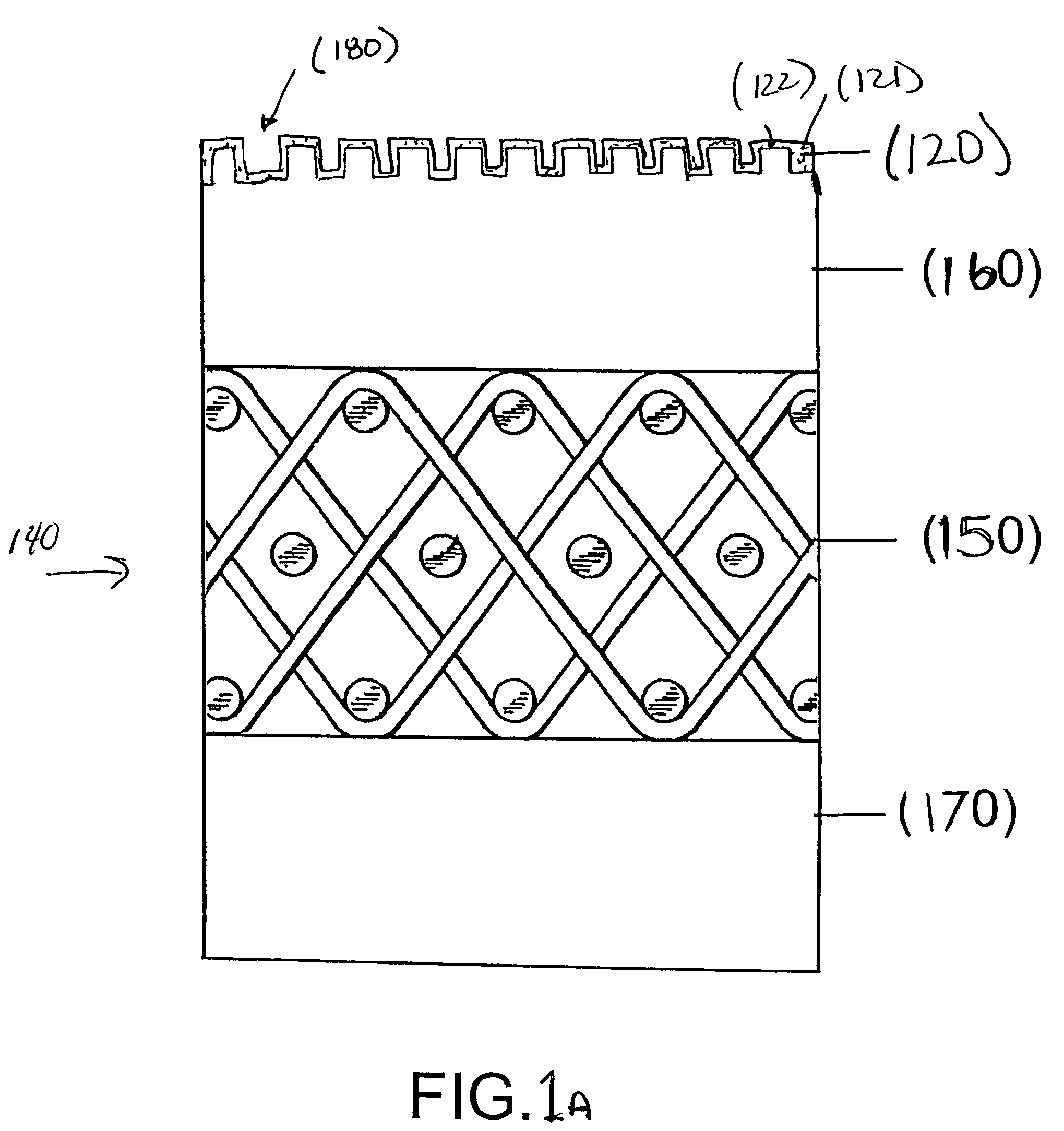
  • Thermally sprayed protective coating for industrial and engineered fabrics
  • Thermally sprayed protective coating for industrial and engineered fabrics
  • Thermally sprayed protective coating for industrial and engineered fabrics

Examples


Embodiment Construction

[0035]The present invention may be used in a variety of applications and industries requiring fabrics or belts including but not limited to industrial fabrics or belts, engineered fabrics or belts, papermachine clothing (PMC) and includes the types of fabrics and belts as aforesaid. Note as earlier mentioned, such a fabric or belt includes or comprises a base support structure, which may itself be sprayed or coated to create a layer thereon or at discrete locations thereon or depositing discrete particles thereon in accordance with the present invention. It should be noted that the terms coating and layer may be used somewhat interchangeably herein. Coating can be used to create a layer. Accordingly, the context in which the term is used and the intended meaning being conveyed will be apparent to one skilled in the art.

[0036]The characteristics or functions of the fabric, belt or even component thereof envisioned to be affected by the thermal spraying include functional properties t...


PUM

PropertyMeasurementUnit
thicknessaaaaaaaaaa
particle sizeaaaaaaaaaa
temperaturesaaaaaaaaaa

Abstract

A fabric or belt and a method for forming such a fabric or belt, including a base support structure and at least one coating with the coating being applied by a thermal spray process.

Description

FIELD OF THE INVENTION[0001]The present invention relates to industrial and engineered fabrics and belts. More specifically, the present invention relates to fabrics and belts and methods of modifying them using thermal spray processes.BACKGROUND OF THE INVENTION[0002]The present invention relates to the papermaking arts including fabrics and belts used in the forming, pressing and drying sections of a paper machine, and to industrial process fabrics and belts, engineered fabrics and belts, along with corrugator belts generally.[0003]The fabrics and belts referred to herein may include those also used in the production of, among other things, wetlaid products such as paper and paper board, and sanitary tissue and towel products made by through-air drying processes; corrugator belts used to manufacture corrugated paper board and engineered fabrics used in the production of wetlaid and drylaid pulp; in processes related to papermaking such as those using sludge filters and chemiwasher...

Claims


Application Information

Patent Timeline
Patent Type & Authority Patents(United States)
IPC IPC(8): B32B3/00H05H1/26B32B5/02B05D1/10B05D1/08B32B27/12D03D25/00
CPCD21F1/0027D21F3/0227D21F3/0236Y10T428/24802Y10S162/902Y10T442/2475Y10T442/2369Y10T442/20Y10T442/273Y10T442/30Y10T442/2279Y10T442/2418Y10T442/2262Y10T442/2213Y10T442/2631Y10T442/2311D21F1/00D21F3/02B05D1/10
Inventor SALITSKY, JOSEPHABERG, BO-CHRISTER
Owner ALBANY INT CORP
Learn More