
Method, system, and device for optimizing a vehicle's suspension

a technology for optimizing and optimizing the suspension of vehicles, applied in cycle equipment, instruments, transportation and packaging, etc., can solve the problems of no shock system used in the development of passive vehicle suspensions, cost and time associated with testing the vehicle, and the seven-post shaker is an expensive piece of test equipment used

Inactive Publication Date: 2011-11-15
ARNOTT T&P HLDG LLC
View PDF13 Cites 101 Cited by
  • Summary
  • Abstract
  • Description
  • Claims
  • Application Information

AI Technical Summary

Benefits of technology

"The invention is a way to optimize the suspension of a vehicle by using a system of modified shocks with sensors and an electronic control unit. The sensors measure the vehicle's movement and the control unit adjusts the damping forces of the shocks to mimic the standard suspension. This results in a smoother ride and better handling for the vehicle."

Problems solved by technology

The seven post shaker is an expensive piece of test equipment used to perform vehicle dynamics analysis for any vehicles, but is mainly used for racecars.
However, no shock systems have been used in the development of passive vehicle suspensions.
One problem with the seven post test is the cost and time associated with testing the vehicle.
The cost of testing a vehicle on a seven post machine is very expensive and is typically calculated on a per hour basis.
This time is a significant factor in the total price of running a vehicle on a seven post test.
Furthermore, most teams have only one seven post rig used to test multiple cars which all need to be tested on the rig before each race, which only compounds the time required for manually adjusting or changing out shocks.
In addition to the time and cost factor associated with manually adjusting and changing the shocks between test cycles, there is also a great risk of human error in manually adjusting or changing the shocks.
Any slight human error can greatly reduce the accuracy of the seven post test.
Furthermore, the data collected at a standard seven post testing facility is limited to what data the testing facility is capable of collecting.

Method used


Image

  • Method, system, and device for optimizing a vehicle's suspension
  • Method, system, and device for optimizing a vehicle's suspension
  • Method, system, and device for optimizing a vehicle's suspension

Examples


Embodiment Construction

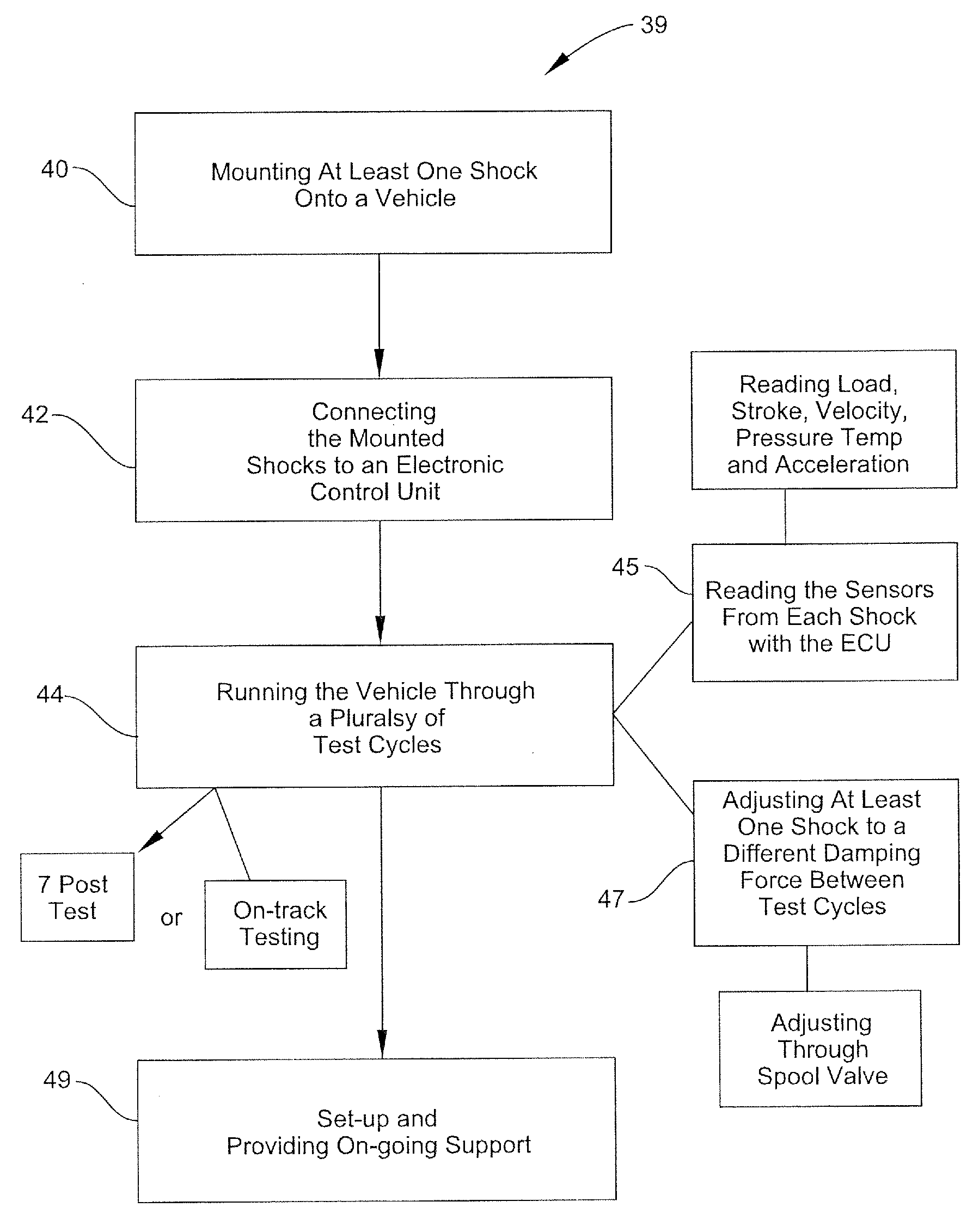
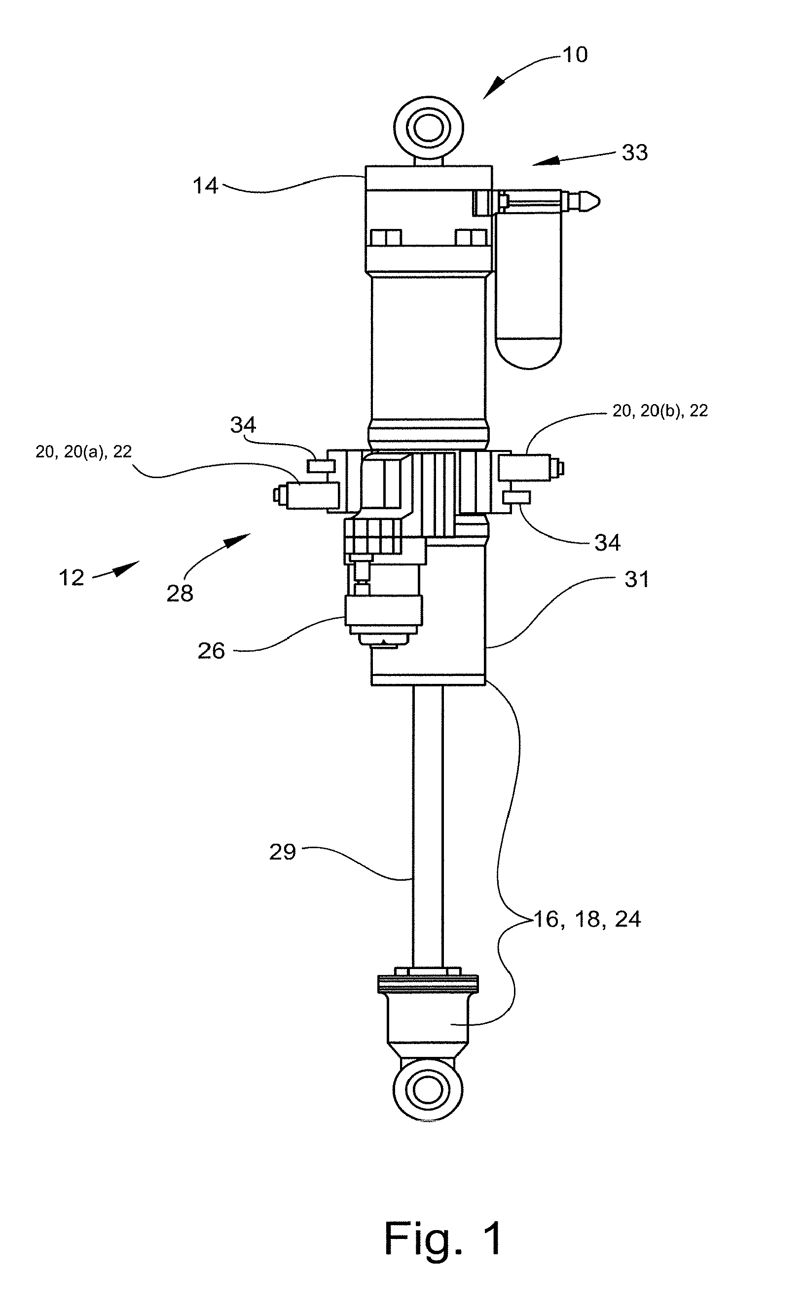
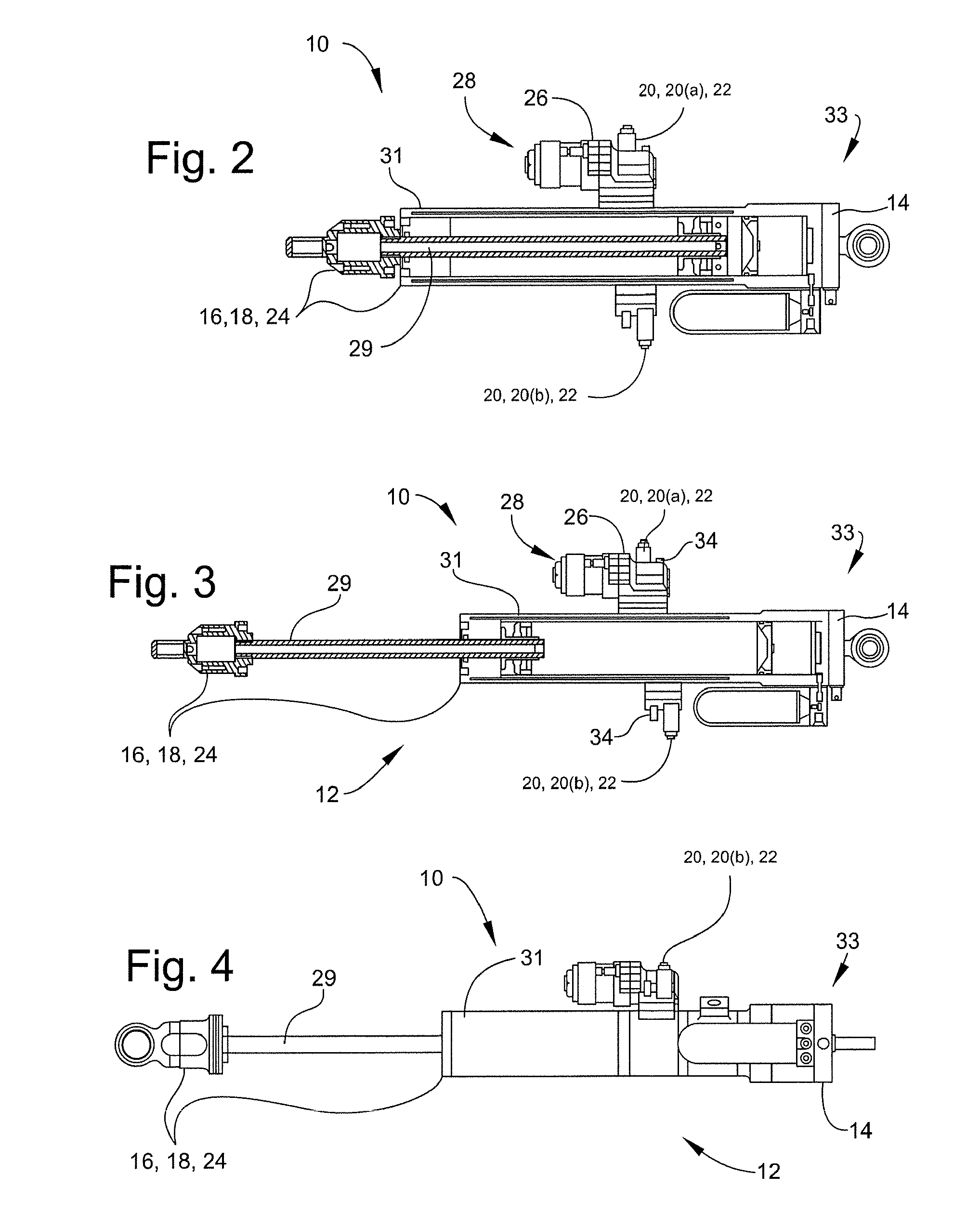
[0025]Referring to the drawings, wherein like numerals indicate like elements, there is shown in FIGS. 1-4 an embodiment of a shock 10 for optimizing a vehicle's suspension. Shock 10 may include a modified passive shock. Shock 10 may be used in optimizing the suspension of any vehicle, including, but not limited to, an automobile 46, and more specifically a racecar. The racecar may be any racecar, including, but not limited to, a NASCAR® racecar. Shock 10 may be used to optimize the suspension of the vehicle utilizing any testing procedure or mechanism, including, but not limited to a seven post shaker, also known as a seven post test. Shock 10 may also be utilized for optimizing the suspension of a vehicle through on-car track testing. Shock 10 may accurately emulate any standard passive shock by duplicating the internal hydraulics of the standard passive shock. The modifications to the passive shock are discussed in great detail below. However, the instant invention is not limited...


PUM


Abstract

A method, system, and device for optimizing a vehicle's suspension includes: mounting at least one modified passive shock with a plurality of sensors onto a vehicle, where the shock is adjustable for a plurality of damping forces; connecting the shock to an electronic control unit being for adjusting the damping forces of the shock and reading the plurality of sensors; and running the vehicle through a plurality of test cycles where the electronic control unit reading the plurality of sensors during each test cycle and adjusting the shock to a different damping force between each test cycle, where the adjusted shock emulating the damping forces of multiple standard passive shocks.

Description

CROSS-REFERENCE TO RELATED APPLICATIONS[0001]This application claims priority to U.S. Provisional Patent Application Ser. No. 61 / 009,605, filed Dec. 31, 2007, which is incorporated herein by reference.FIELD OF INVENTION[0002]The instant invention relates to a method, system, and device for optimizing a vehicle's suspension.BACKGROUND OF THE INVENTION[0003]The present invention relates to a method, system and device for optimizing the suspension of a vehicle, and, in particular for optimizing the suspension of a race car.[0004]In the automobile design industry and in automobile racing, optimizing the suspension of a vehicle is critical to the vehicle's performance. The current practice includes, running the vehicle or race car through a plurality of test cycles using different suspension setups which have to be manually adjusted, and then taking the results of those tests to determine the optimal suspension design. The test cycles could include many different types of tests, includin...

Claims


Application Information

Patent Timeline
Patent Type & Authority Patents(United States)
IPC IPC(8): G01M17/04
CPCB60G17/018B60G17/06G01M17/04B60G2400/102B60G2400/202B60G2400/252B60G2400/5182B60G2400/60B60G2400/7162
Inventor RYAN, JEFFREY SCOTTNEGISHI, NOBUHIKO
Owner ARNOTT T&P HLDG LLC
Learn More