
Dispersion-shifted optical fiber

a technology of optical fiber and shifted fiber, applied in the field of optical fiber transmission, can solve the problems of introducing more significant rayleigh scattering loss, attenuation larger, attenuation in optical fiber, etc., and achieve the effect of limiting bending loss

Active Publication Date: 2011-11-08
DRAKA COMTEQ BV
View PDF71 Cites 30 Cited by
  • Summary
  • Abstract
  • Description
  • Claims
  • Application Information

AI Technical Summary

Benefits of technology

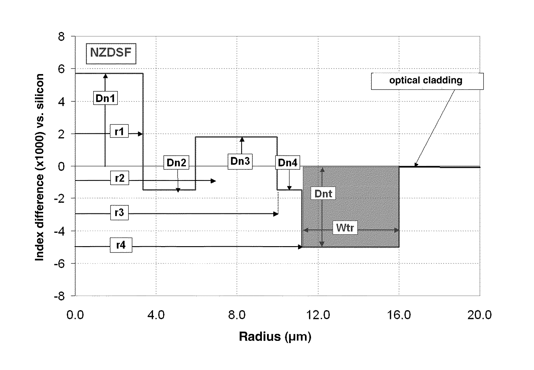
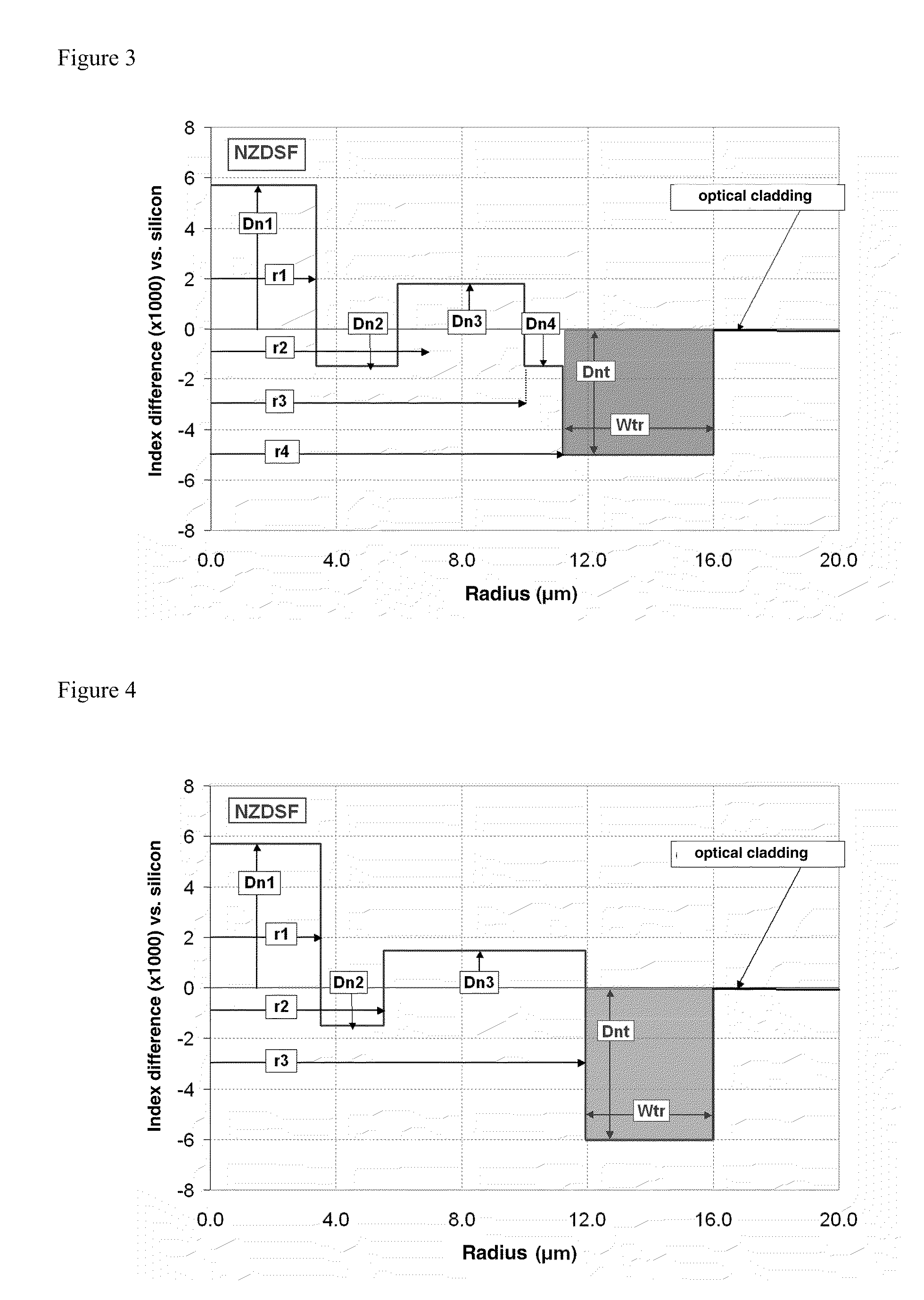
The invention proposes an NZDSF that achieves an attenuation close to that of an SSMF while limiting bending losses and observing the standards relating to NZDSFs, notably in term of dispersion, effective area, and cut-off wavelength. The NZDSF includes a central core, inner cladding including at least three zones, and an optical cladding. The central core has a radius and an index difference with the optical cladding. The inner cladding has a radius and an index difference with the optical cladding. The NZDSF has Rayleigh scattering losses less than or equal to 0.164 dB / km at the wavelength of 1550 nm, bending losses less than 0.5 dB / turn for a bending radius of 16 millimeters at the wavelength of 1550 nm, and bending losses less than 0.5 dB / 100 turns for a bending radius of 30 millimeters at 1625 nm. The optical fiber has one or more of the following characteristics: the central core has an index difference with the optical cladding of less than 7.5×10⁻³; the index difference of the intermediate cladding zone with the optical cladding is between −2.5×10⁻³ and 1.5×10⁻³; the index difference of the ring zone with the optical cladding is between 0.0 and 5×10⁻³; the radius of the core is between 2 μm and 4.35 μm; the outer radius of the intermediate cladding zone is between 4.5 μm and 8.5 μm; the ring zone has a width between 3 μm and 7.5 μm; the inner radius of the buried trench zone is larger than 10 μm; the outer radius of the buried trench zone is less than or equal to 17 μm; the fiber has, for a wavelength of 1550 nm, a chromatic dispersion of less than 12 ps / (nm·km)); the fiber has, for a wavelength of 1550 nm, a chromatic dispersion slope of less than or equal to 0.09 ps / (nm2·km)); the fiber has an effective cut-off wavelength of less than 1600 nm; and the fiber has an effective area larger than 50 μm2.

Problems solved by technology

The more significant doping of the core as compared with an SSMF, however, introduces more significant Rayleigh scattering losses, larger than 0.164 dB / km leading to an attenuation larger than 0.190 dB / km at 1550 nm.
The attenuation in an optical fiber is due mostly to Rayleigh scattering losses and partly to absorption losses and to losses due to defects of the guide.
In the case of an NZDSF, the presence of dopants in the core in a higher concentration as compared with an SSMF, increases losses by Rayleigh scattering.
The fibers with a pure silica core, however, are costly to manufacture because of the obligation of burying the optical cladding by doping (e.g., with fluorine).
The proposed solutions are complex to apply industrially, however, because several fiber-drawing temperatures are used with heating and cooling cycles, which are difficult to control.
The method proposed in this document however requires complex equipment with additional cooling devices.
Such a solution is however costly and not directly applicable to an NZDSF type fiber.
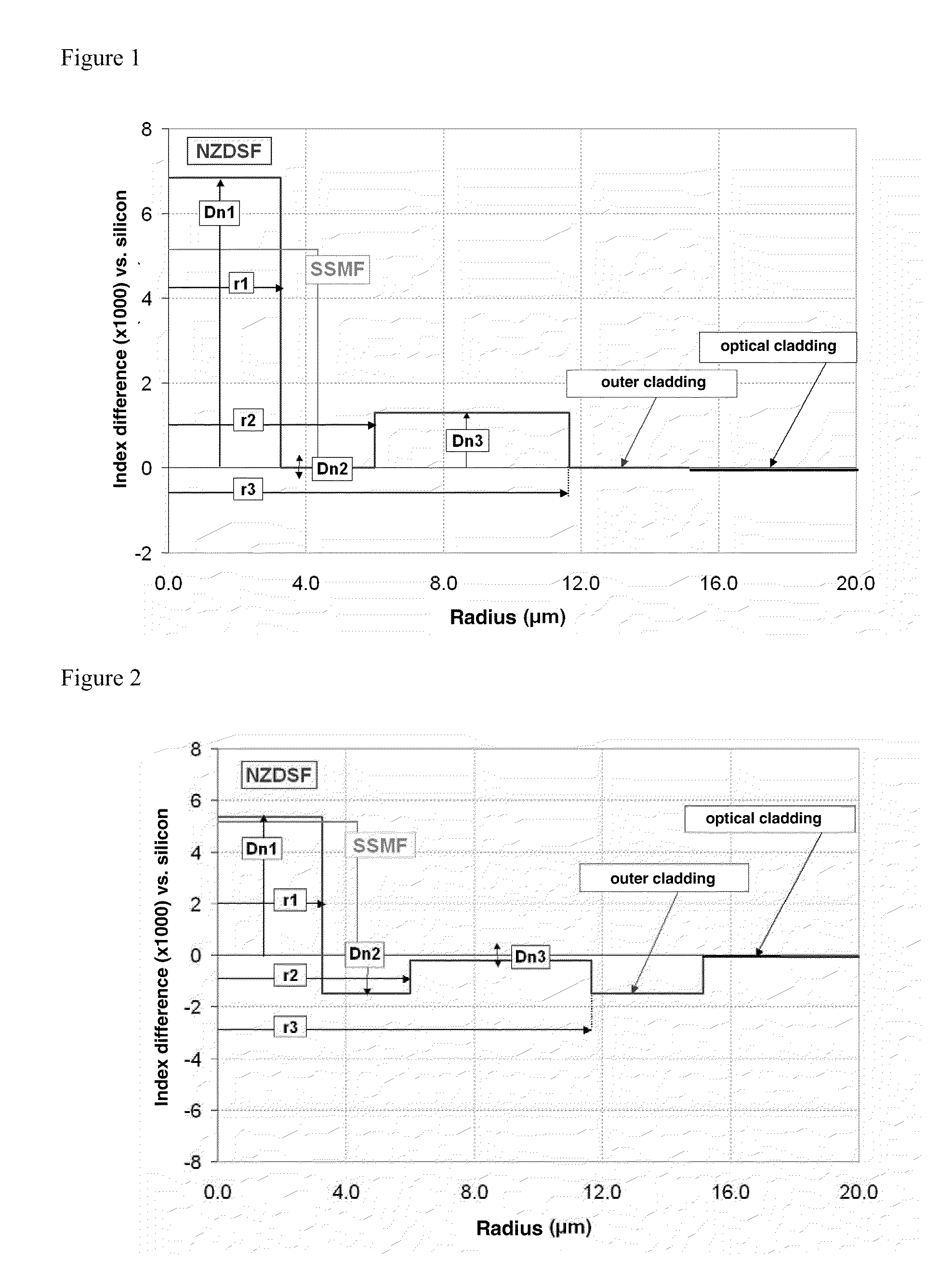
However, by simply adding a buried trench to the structure proposed in FIG. 2, it is not possible to reach acceptable bending losses as this is shown by Example 2b of the Tables I and II (below).

Method used


Image

  • Dispersion-shifted optical fiber
  • Dispersion-shifted optical fiber
  • Dispersion-shifted optical fiber

Examples


Embodiment Construction

[0043]The fiber according to the invention is a non-zero dispersion-shifted fiber that has a chromatic dispersion lower than the chromatic dispersion of a standard step-index SSMF. The fiber according to the invention has reduced Rayleigh scattering losses (e.g., less than 0.164 dB / km at 1550 nm). The fiber according to the invention further has limited bending losses (e.g., less than 0.5 dB / turn for a bending radius of 16 millimeters at 1550 nm and less than 0.5 dB / 100 turns for a bending radius of 30 millimeters at 1625 nm.

[0044]The fiber of the invention will be described with reference to FIGS. 3 and 4, which illustrate set profiles for two possible embodiments.

[0045]The NZDSF according to the invention includes a central core having an index difference Dn1 with an outer cladding, acting as an optical cladding, and at least three inner cladding zones between the central core and the optical cladding. In this context, the central core and the inner cladding zones are obtained by ...


PUM


Abstract

A dispersion-shifted optical fiber (NZDSF) includes a central core (r1, Dn1), an inner cladding having at least three zones with a first intermediate cladding zone (r2, Dn2), a second ring zone (r3, Dn3) and a third buried trench zone (Wtr, Dnt). The buried trench zone has an index difference (Dnt) with the optical cladding between −5·10−3 and −15·10−3 and has a width (Wtr) between 2.5 μm and 5.5 μm. The present optical fiber, at a wavelength of 1550 nm, has reduced Rayleigh scattering losses of less than 0.164 dB / km, with limited bending losses.

Description

CROSS-REFERENCE TO PRIORITY APPLICATION[0001]This application claims the benefit of pending French application Ser. No. 08 / 01868 for “Dispersion Shifted Optical Fiber” (filed Apr. 4, 2008, at the French Patent Office), which is hereby incorporated by reference in its entirety.FIELD OF THE INVENTION[0002]The present invention relates to the field of optical fiber transmissions and, more specifically, to a dispersion-shifted fiber having reduced attenuation without an increase in bending losses.BACKGROUND OF THE INVENTION[0003]A refractive index profile of an optical fiber is a graphical representation of the value of the refractive index as a function of optical fiber radius. Conventionally, the distance r to the center of the optical fiber is shown along the abscissa (i.e., the x axis), and the difference between the refractive index at radius r and the refractive index of the outer optical cladding of the optical fiber is shown along the ordinate axis (i.e., the y axis). The outer ...

Claims


Application Information

Patent Timeline
Patent Type & Authority Patents(United States)
IPC IPC(8): G02B6/02
CPCG02B6/03661G02B6/02014G02B6/02271
Inventor SILLARD, PIERREREGNIER, ELISEBIGOT-ASTRUC, MARIANNEMOLIN, DENISDE MONTMORILLON, LOUIS-ANNERICHARD, SIMON
Owner DRAKA COMTEQ BV
Learn More