
Piezoelectric speaker

a piezoelectric speaker and speaker body technology, applied in the field of thin-type piezoelectric speakers, can solve the problems of difficult to provide a suitable fixation device at one end for mounting, difficult to fix the fixation device to another object, and easy to disconnect the fixation device from the object, so as to prevent an excessive high frequency during operation, facilitate installation, and high output sound quality

Inactive Publication Date: 2011-11-08
YANG SU PEI +1
View PDF2 Cites 3 Cited by
  • Summary
  • Abstract
  • Description
  • Claims
  • Application Information

AI Technical Summary

Benefits of technology

The present invention has been accomplished under the circumstances in view. It is one object of the present invention to provide a piezoelectric speaker, which is easy to install. It is another object of the present invention to provide a piezoelectric speaker, which provides a high output sound quality. It is still another object of the present invention to provide a piezoelectric speaker, which prevents an excessive high frequency during operation.

Problems solved by technology

Because a longitudinal vibrator or piezoelectric polymer for speaker has a small size, it is difficult to provide a suitable fixation device at its one end for mounting.
Even if a longitudinal vibrator or piezoelectric polymer is provided with a fixation device, it is still difficult to fix the fixation device to another object.
After fixation of the fixation device to another object, the fixation device may be disconnected from the object easily by accident.
These electric wires or signal lines complicate the installation procedure of the piezoelectric speaker in, for example, a cell phone, multimedia player or notebook computer.

Method used


Image

  • Piezoelectric speaker
  • Piezoelectric speaker
  • Piezoelectric speaker

Examples


Embodiment Construction

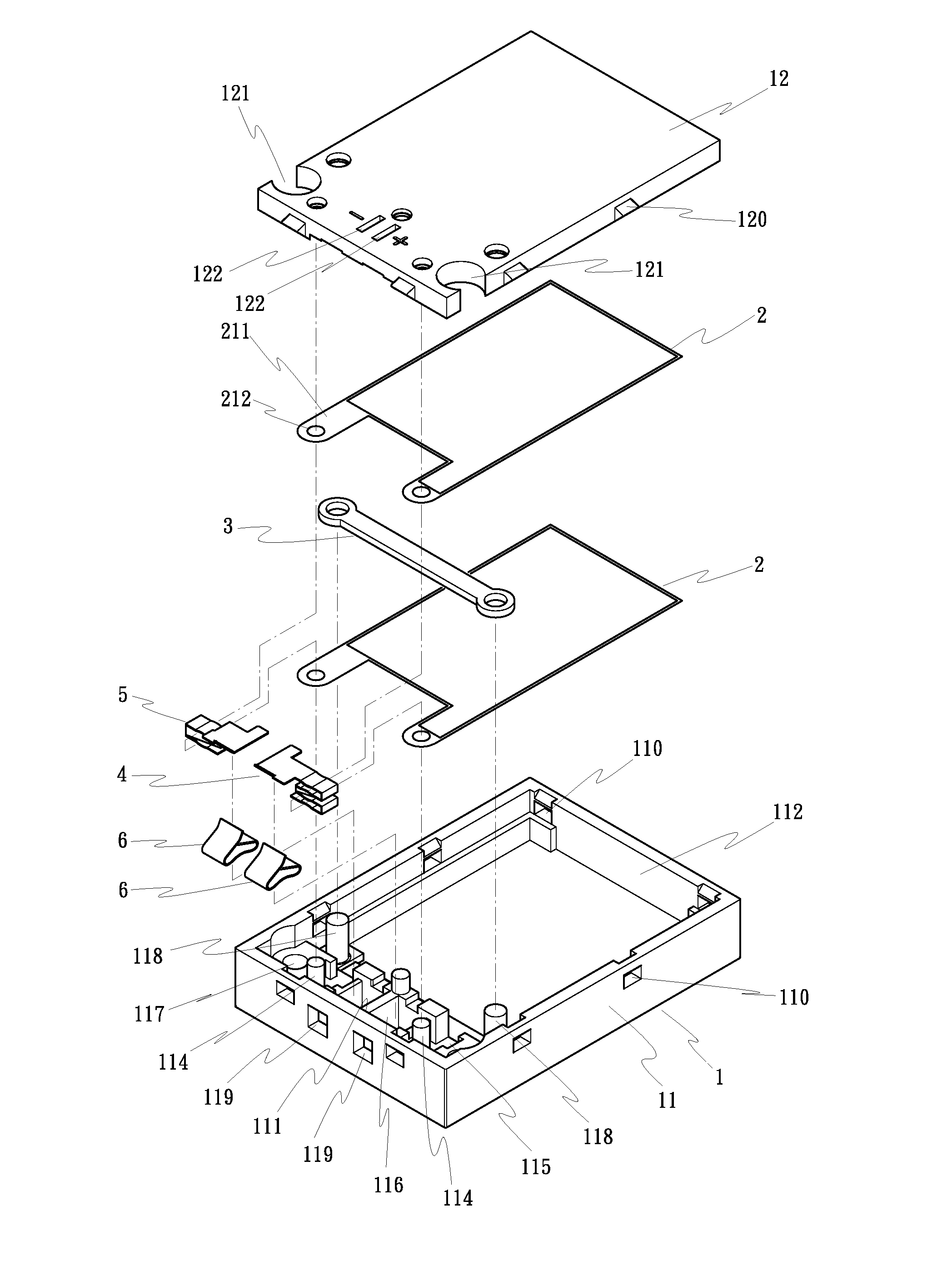
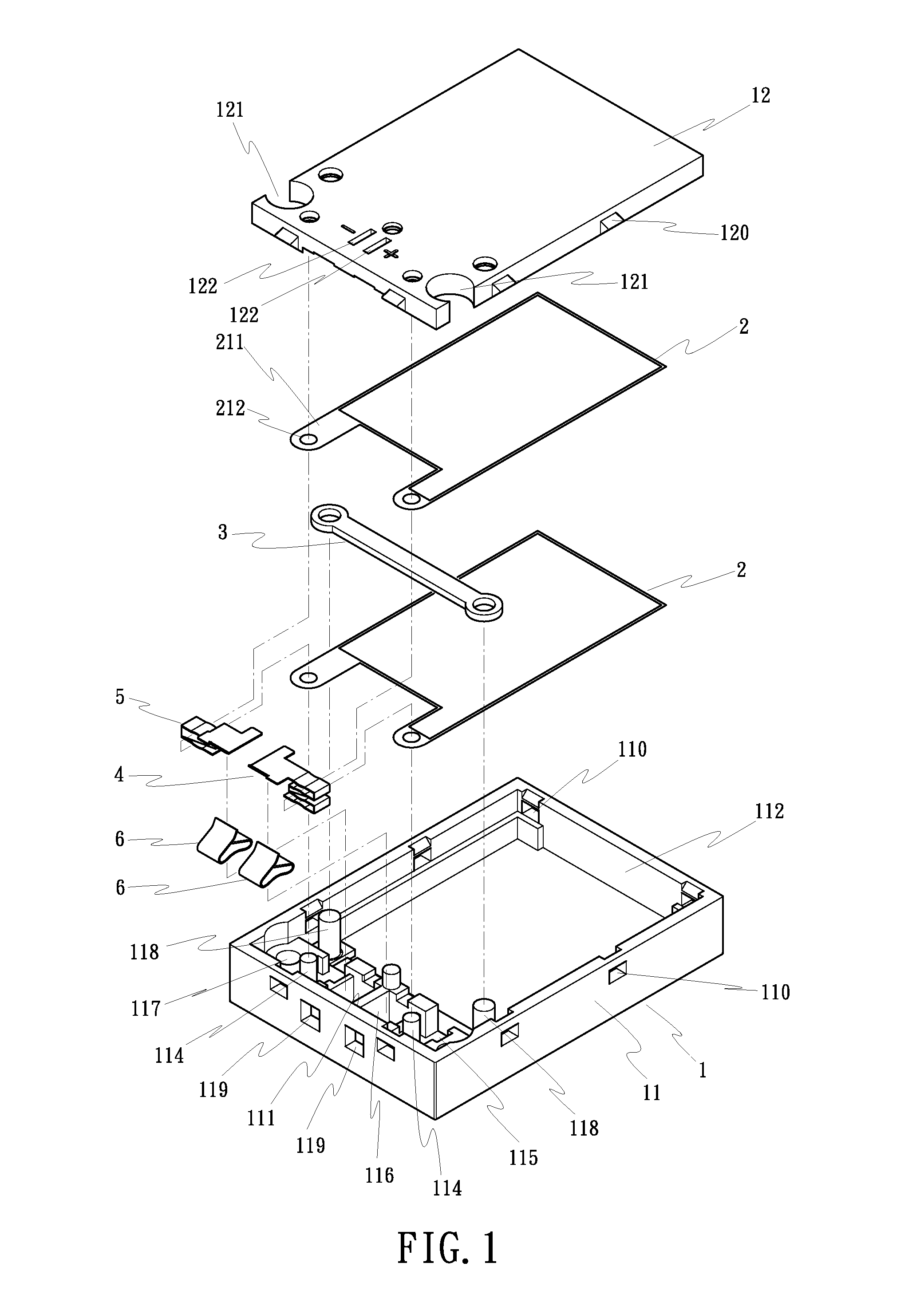
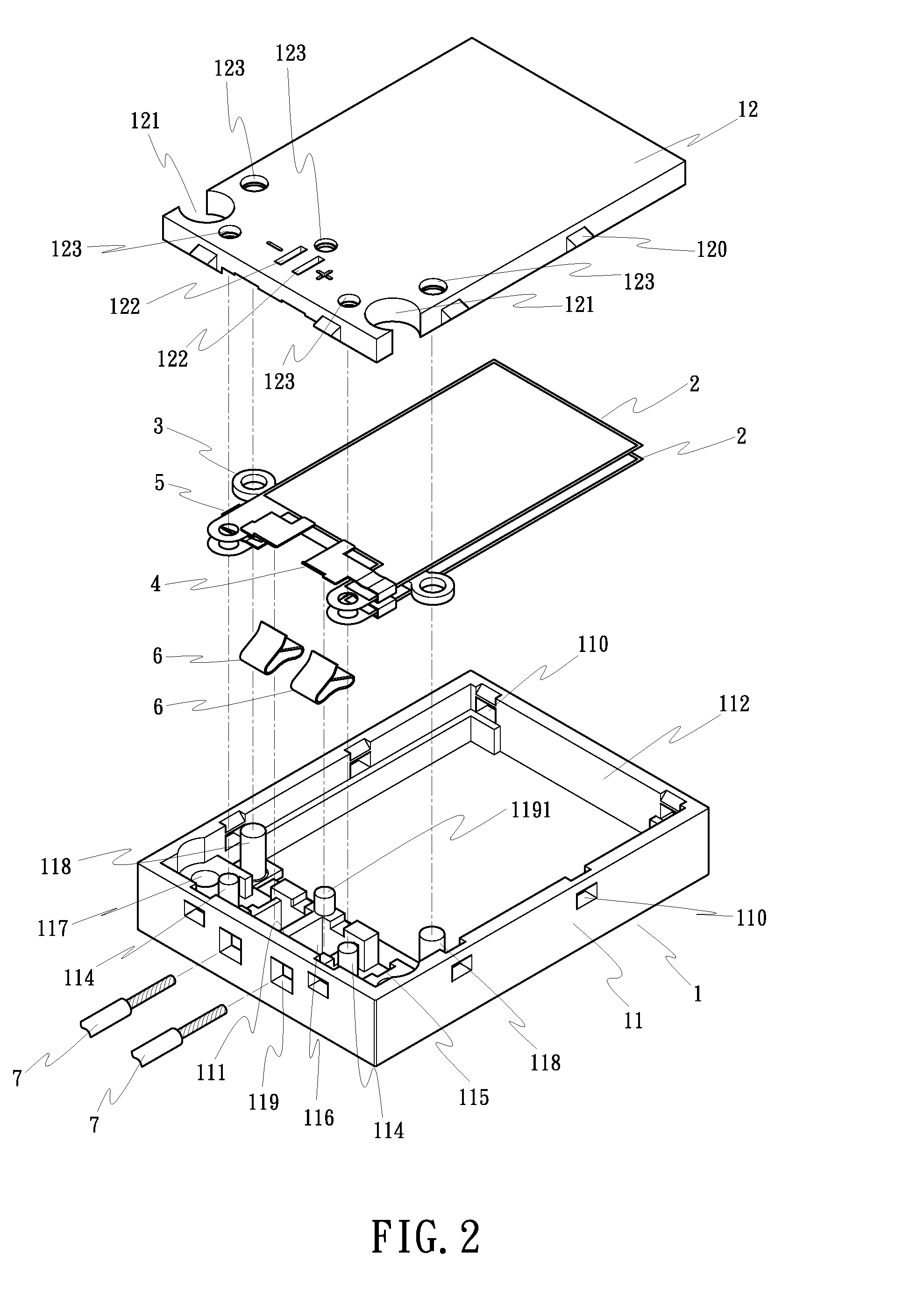
Referring to FIGS. 1˜6, a piezoelectric speaker in accordance with the present invention comprises a cabinet 1, two piezoelectric vibrators 2, a shock absorber 3, two conducting terminals 4 and 5, and two clamps 6.

The cabinet 1 (see FIGS. 1 and 3) is a hollow enclosed box formed of a box body 11 and a box cover 12. The box body 11 is a rectangular container (see FIGS. 5 and 6) defining a fixed end 111 and a free end 112. The box body 11 has two parallel wells 113 inside the fixed end 111, two locating members, for example, locating rods 114 respectively provided inside the wells 113 for securing the piezoelectric vibrators 2, two mounting portions, for example, mounting notches 115 respectively and transversely disposed in the wells 113 at one side for securing the conducting terminals 4 and 5, two accommodation grooves 116 respectively disposed adjacent to the locating rods 114 for accommodating the clamps 6, two vertical screw holes 117 respectively disposed in the wells 113 near ...


PUM


Abstract

A piezoelectric speaker includes a cabinet, piezoelectric vibrators horizontally mounted inside the cabinet at different elevations each having two eyed lugs respectively coupled to respective posts in the cabinet, a shock absorber coupled to the piezoelectric material of the piezoelectric vibrators, two conducting terminals accommodated inside the cabinet and clamped on the piezoelectric vibrators, and two clamps fastened to the conducting terminals to secure a respective signal line.

Description

BACKGROUND OF THE INVENTION(a) Field of the InventionThe present invention relates to speakers and, more particularly, to a thin-type piezoelectric speaker.(b) Description of the Prior ArtPiezoelectricity is the ability of crystals to generate a voltage in response to applied mechanical stress. Piezoelectric materials such as piezoelectric crystals, Rochelle salt, ceramics of barium titanate series, etc., are widely used. Longitudinal vibrator type, dual-state type, piezoelectric polymer type, and many other types of piezoelectric speakers are known to have thin and small-sized characteristics. A longitudinal vibrator type or piezoelectric polymer type speaker has a defined end connected to another body so that sound can be produced when electrically connected. Therefore, a longitudinal vibrator or piezoelectric polymer may have a fixation device at one end thereof for mounting, for example, for fastening to a cell phone, multimedia player, notebook computer, etc.Because a longitudi...

Claims


Application Information

Patent Timeline
Patent Type & Authority Patents(United States)
IPC IPC(8): H01L41/053H04R7/22H01L41/09H04R1/02
CPCH04R17/00
Inventor YANG, SU-PEILAI, ING-MING
Owner YANG SU PEI
Learn More