
Method for manufacturing magnetic recording medium and magnetic recording and reproducing apparatus

a technology of magnetic recording and reproducing apparatus, which is applied in the direction of electric/magnetic/electromagnetic heating, instruments, and record information storage, etc., can solve the problems of affecting reducing bit error rate, and hindering the enhancement of recording density, so as to ensure the stability of head floating, prevent possible adverse effects, and excellent separation ability

Inactive Publication Date: 2011-11-01
SHOWA DENKO KK
View PDF23 Cites 11 Cited by
  • Summary
  • Abstract
  • Description
  • Claims
  • Application Information

AI Technical Summary

Benefits of technology

[0030]The present invention can provide a magnetic recording medium manufactured by forming the magnetic recording patterns after forming the magnetic layer on the nonmagnetic substrate, the magnetic recording medium enabling the stability of head floating to be ensured, having an excellent capability of separating the magnetic recording patterns from one another, preventing the possible adverse effect by the interference between signals from the adjacent patterns, and offering an excellent recording density property. The present invention can also eliminate the need for the following steps from the magnetic layer processing method, which has been considered to be very complicated: a step of removing the magnetic layer by dry etching, a subsequent burying step, and a subsequent step of re-burying etched-away portions to form a film. This contributes significantly to enhancing the productivity.
[0031]Furthermore, the magnetic recording and reproducing apparatus in accordance with the present invention uses the magnetic recording medium in accordance with the present invention. The present invention thus provides a magnetic recording and reproducing apparatus having an excellent head floating property, having an excellent capability of separating the magnetic recording patterns from one another, and preventing the possible adverse effect by the interference between signals from the adjacent patterns, thus offering an excellent recording density property.

Problems solved by technology

However, increasing the track density is disadvantageously likely to cause magnetically recorded data in adjacent tracks to interfere with each other.
This leads directly to a decrease in bit error rate, hindering the enhancement of the recording density.
However, a reduction in the size of recording bits may disadvantageously decrease the minimum magnetization volume per bit, resulting in heat fluctuation.
However, this may disadvantageously make it difficult to obtain sufficient reproduction outputs and to thus ensure a sufficient SNR.
Unfortunately, the medium is thus prone to be contaminated during the manufacturing process, which is very complicated.
However, the film formed takes over the recess and protrusion shapes formed on the substrate, preventing the stabilization of the floating posture and height of a recording and reproducing head performing the recording and reproducing operations while floating over the medium.
However, the inter-track regions formed by this method offer reduced saturation magnetization but increased coersive force.
Consequently, an insufficient magnetization state remains, resulting in blurring when information is written on the magnetic track portion.
However, even with this method, disadvantageously, the magnetic recording medium may be contaminated during the manufacturing process.
Furthermore, the smoothness of the surface may be degraded.

Method used


Image

  • Method for manufacturing magnetic recording medium and magnetic recording and reproducing apparatus
  • Method for manufacturing magnetic recording medium and magnetic recording and reproducing apparatus
  • Method for manufacturing magnetic recording medium and magnetic recording and reproducing apparatus

Examples


example 1

[0075]A vacuum chamber with a glass substrate for an HD set therein was pre-evacuated to 1.0×10⁻⁵ Pa or less. The material for the glass substrate was crystallized glass composed of Li2Si2O5, Al2O3—K2O, MgO—P2O5 or Sb2O3—ZnO. The glass substrate had an outside diameter of 65 mm, an inside diameter of 20 mm and an average surface roughness (Ra) of 2 Å.

[0076]Thin films were sequentially stacked on the glass substrate. Specifically, a soft magnetic layer of FeCoB, an intermediate layer of Ru and a magnetic layer of 70Co-5Cr-15Pt-10SiO2 alloy were first deposited in this order using the DC sputtering, and a protective film layer of C (carbon) was then formed by the P-CVD method. The FeCoB soft magnetic layer had a film thickness of 600 Å. The Ru intermediate layer had a film thickness of 100 Å. The magnetic layer had a film thickness of 150 Å. The C (carbon) protective film layer had an average film thickness of 2 nm.

[0077]A mask layer was formed on the resultant stacked structure by sp...

examples 2 to 28

[0082]Magnetic recording media were manufactured under conditions similar to those in Example 1 except for the material and film thickness of the mask which were changed as shown in Table 1. In Example 28, the resist material was changed from the novolac resin to a thermosetting resin, and the curing treatment was changed from the ultraviolet irradiation to a heat treatment at 150° C. for 30 minutes.


PUM

PropertyMeasurementUnit
thicknessaaaaaaaaaa
angleaaaaaaaaaa
thicknessaaaaaaaaaa

Abstract

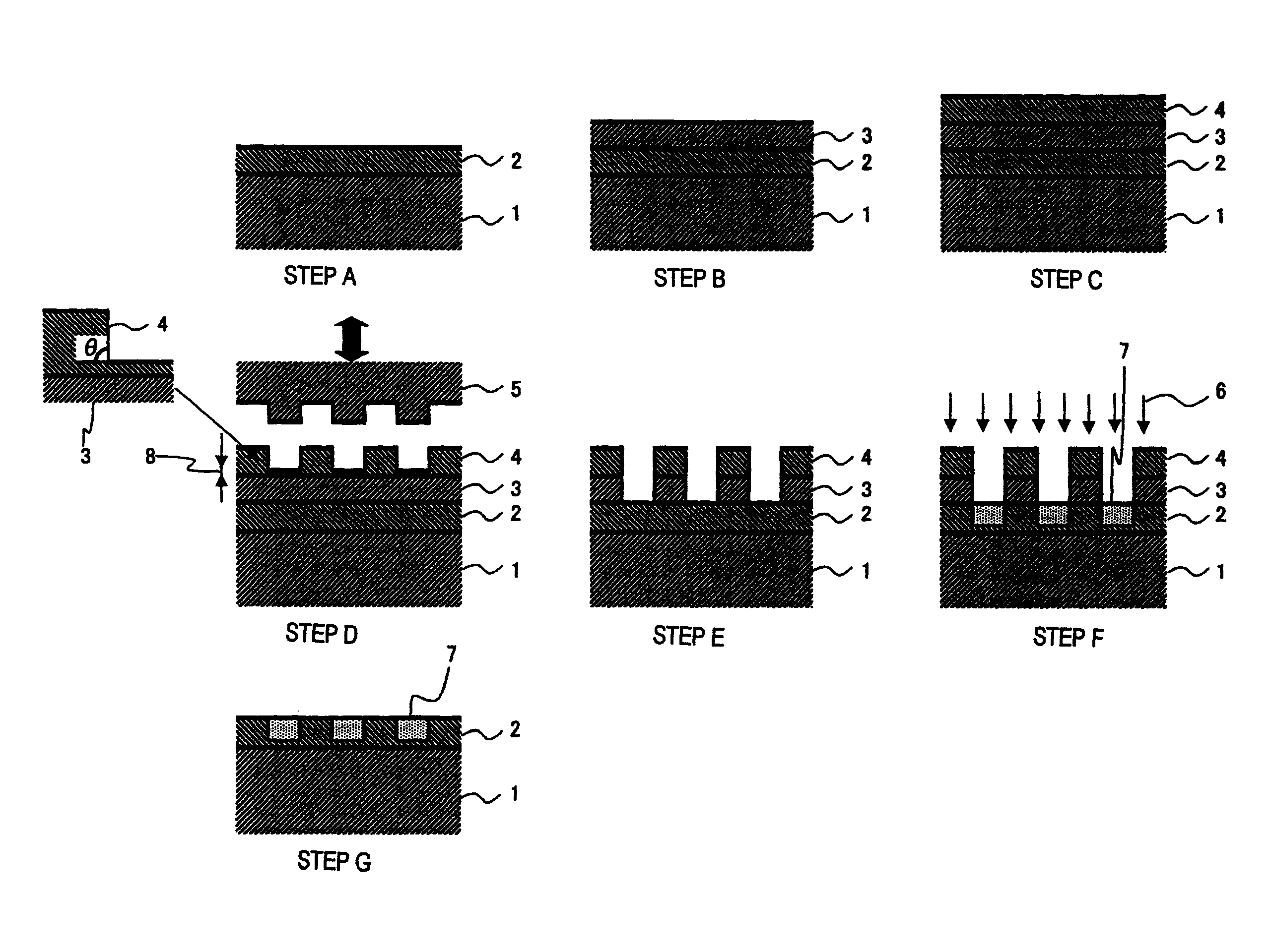
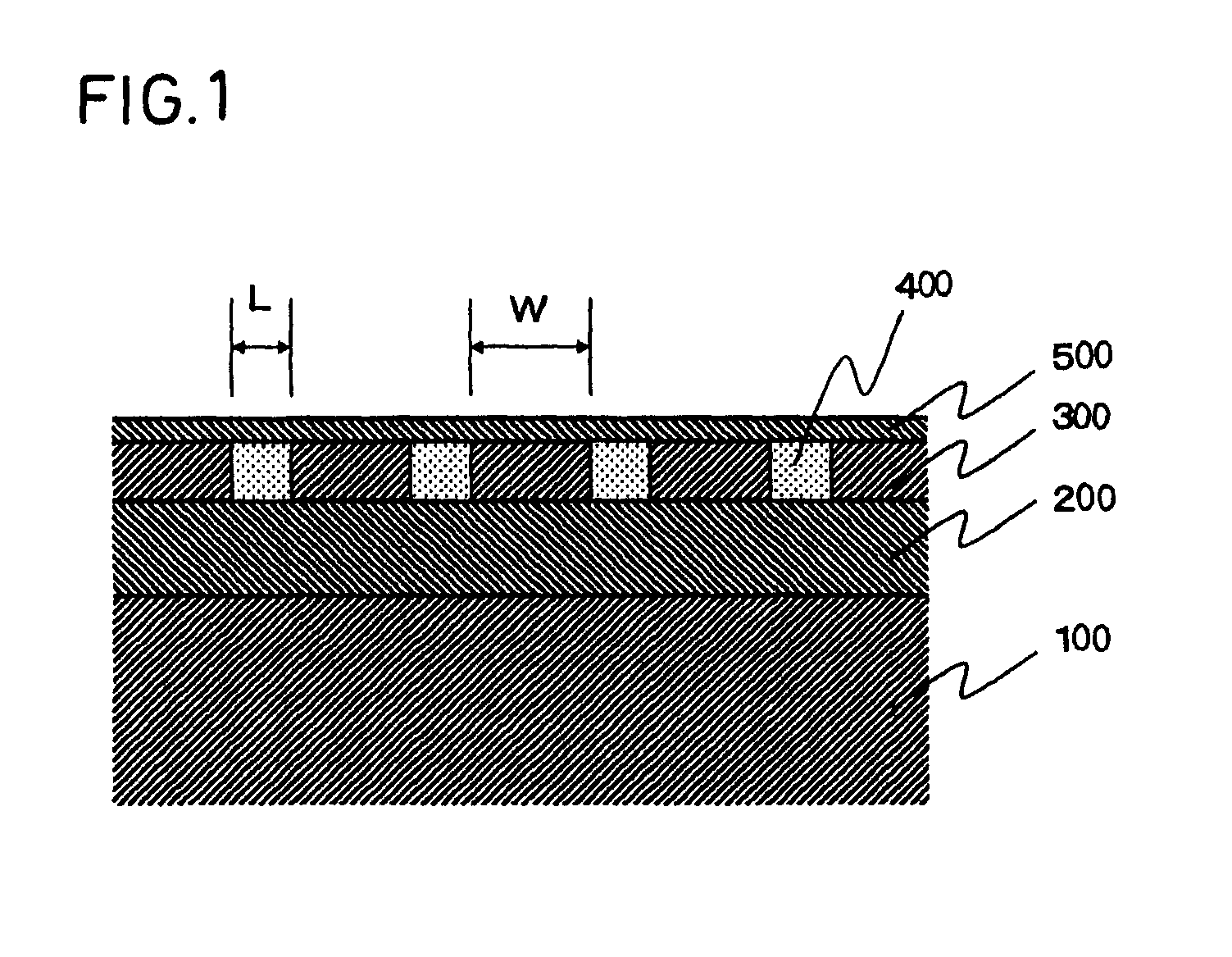
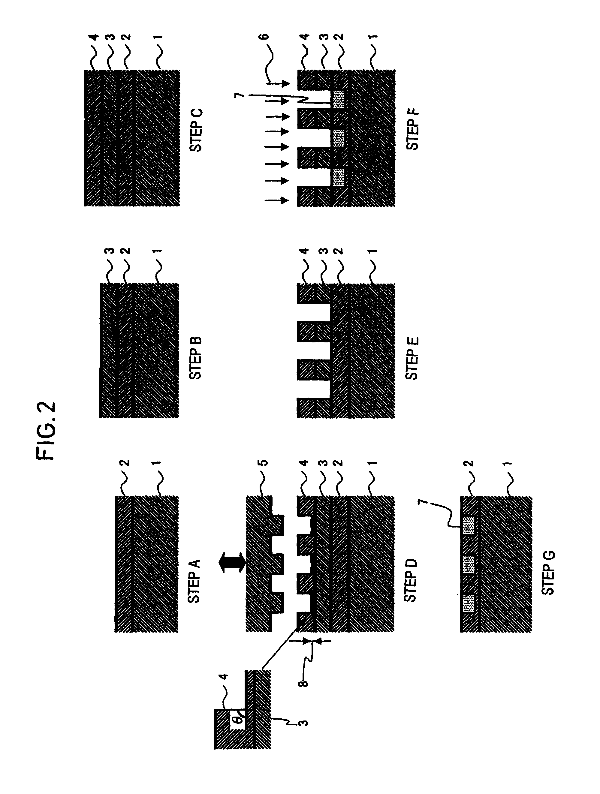
A method for manufacturing a magnetic recording medium (30) having magnetically separate magnetic recording patterns on at least one surface of a nonmagnetic substrate (1), includes the steps of forming a magnetic layer (2) on the nonmagnetic substrate, forming a mask layer (3) on the magnetic layer, forming a resist layer (4) on the mask layer, transferring negative patterns of the magnetic recording patterns to the resist layer using a stamp (5), removing portions of the mask layer which correspond to the negative patterns of the magnetic recording patterns, implanting ions in the magnetic layer from a resist layer-side surface to partly demagnetize the magnetic layer, and removing the resist layer and the mask layer. A magnetic recording and reproducing apparatus includes the above magnetic recording medium (30), a driving section (11) that drives the magnetic recording medium in a recording direction, a magnetic head (27) including a recording section and a reproducing section, a device (28) for moving the magnetic head relative to the magnetic recording medium, and recording and reproducing signal processing device (29) for inputting a signal to the magnetic head and reproducing an output signal from the magnetic head.

Description

CROSS REFERENCE TO RELATED APPLICATION[0001]This application is an application filed under 35 U.S.C. §119(e)(1) of the filing date of Japanese Patent application No. 2006-318839 filed Nov. 27, 2006 pursuant to 35 U.S.C. §111(b).TECHNICAL FIELD[0002]The present invention relates to a method for manufacturing a magnetic recording medium for use in a hard disk drive and the like, and a magnetic recording and reproducing apparatus.BACKGROUND ART[0003]The application range of magnetic recording drives, such as magnetic disk drives, flexible disk drives and magnetic tape drives, has recently been significantly extended, making these magnetic recording drives more important. For magnetic recording media used in these drives, efforts have been made to markedly improve recording density. In particular, since the introduction of an MR head and a PRML technique, surface recording density has been further significantly increased. In recent years, a GMR head and a TMR head have also been introdu...

Claims


Application Information

Patent Timeline
Patent Type & Authority Patents(United States)
IPC IPC(8): G11B5/84
CPCC23C14/0005C23C14/48G11B5/855H01F41/34
Inventor FUKUSHIMA, MASATOSAKAWAKI, AKIRA
Owner SHOWA DENKO KK
Learn More